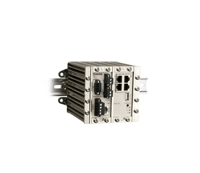
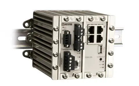
westermo Wolverine DDW-226 Industrial Ethernet SHDSL Extender
General information
Legal information
The contents of this document are provided “as is”. Except as required by applicable law, no warranties of any kind, either express or implied, including, but not limited to, the implied warranties of merchantability and fitness for a particular purpose, are made in relation to the accuracy and reliability or contents of this document. Westermo reserves the right to revise this document or withdraw it at any time without prior notice.
Under no circumstances shall Westermo be responsible for any loss of data or income or any special, incidental, and consequential or indirect damages howsoever caused.
More information about Westermo can be found at www.westermo.com
Software tools
Related software tools are available in the folder software tools under technical support on the Westermo website.
License and copyright for included Free/Libre Open Source Software
This product includes software developed by third parties, including Free/Libre Open Source Software (FLOSS). The specific license terms and copyright associated with the software are included in each software package respectively. Please visit the product web page for more information.
Upon request, the applicable source code will be provided. A nominal fee may be charged to cover shipping and media. Please direct any source code request to your normal sales or support channel.
WeOS Management Guide
This product runs WeOS 4 (Westermo Operation System). Instructions for quick start, configuration, factory reset and use of USB port are found in the WeOS Management Guide at www.westermo.com.
Safety and Regulations
Warning signs are provided to prevent personal injuries and/or damages to the product.
The following levels are used:
| Level of warning | Description | Consequence personal injury | Consequence material damage |
 | Indicates a potentially hazardous situation | Possible death or major injury | Major damage to the product |
 | Indicates a potentially hazardous situation | Minor or moderate injury | Moderate damage to the product |
 | Provides information in order to avoid misuse of the product, confusion or misunderstanding | No personal injury | Minor damage to the product |
 | Used for highlighting general, but important information | No personal injury | Minor damage to the product |
Before installation
Read this manual completely and gather all information on the product. Make sure that you understand it fully. Check that your application does not exceed the safe operating specifications for this product.
| WARNING – SAFETY DURING INSTALLATION The product must be installed by qualified service personnel and built in to an apparatus cabinet or similar, where access is restricted to service personnel only. During installation, ensure a protective earthing conductor is first connected to the protective earthing terminal (only valid for metallic housings). Westermo recommends a cross-sectional area of at least 4 mm2. If the product does not have a protective earthing terminal, then the DIN-rail must be connected to protective earth. Upon removal of the product, ensure that the protective earthing conductor, or the connection to earth via the DIN-rail, is disconnected last. |
| WARNING – HAZARDOUS VOLTAGE Do not open an energized product. Hazardous voltage may occur when connected to a power supply |
| WARNING – PROTECTIVE FUSE It must be possible to disconnect manually from the power supply. Ensure compliance to national installation regulations. Replacing the internal fuse must only be performed by Westermo qualified personell. |
| WARNING – REDUCE THE RISK OF FIRE To reduce the risk of fire, use only telecommunication line cords with a cable diameter of AWG 26 or larger. Regarding power cable dimensions, see Interface Specifications. |
| CAUTION – ELECTROSTATIC DISCHARGE (ESD) Prevent electrostatic discharge damages to internal electronic parts by discharging your body to a grounding point (e.g. use a wrist strap). |
| CAUTION – HOT SURFACE Be aware of that the surface of this product may become hot. When it is operated at high temperatures, the external surface may exceed Touch Temperature Limit according to the product’s relevant electrical safety standard. |
Care recommendations
Follow the care recommendations below to maintain full operation of product and to fulfill the warranty obligations:
- Do not drop, knock or shake the product. Rough handling above the specification may cause damage to internal circuit boards.
- Use a dry or slightly water-damp cloth to clean the product. Do not use harsh chemicals, cleaning solvents or strong detergents.
- Do not paint the product. Paint can clog the product and prevent proper operation.
If the product is used in a manner not according to specification, the protection provided by the equipment may be impaired.
If the product is not working properly, contact the place of purchase, nearest Westermo distributor office or Westermo technical support.
Product disposal
 This symbol means that the product shall not be treated as unsorted municipal waste when disposing of it. It needs to be handed over to an applicable collection point for recycling electrical and electronic equipment.
By ensuring this product is disposed of correctly, you will help to reduce hazardous substances and prevent potential negative consequences to both environment and human health, which could be caused by inappropriate disposal.
Simplified EU declaration of conformity
Hereby, Westermo declares that the equipment is in compliance with EU directives. The full EU declaration of conformity and other detailed information are available at the respective product page at www.westermo.com.
Agency approvals and standards compliance
| Type | Approval / Compliance |
| EMC | EN 61000-6-1, Immunity residential,environments |
| EN 61000-6-2, Immunity industrial environments | |
| EN 61000-6-3, Emission residential environments | |
| EN 61000-6-4, Emission industrial environments | |
| EN 50121-4, Railway signalling and telecommunications apparatus | |
| Safety | UL 60950-1, IT equipment |
| SHDSL | ITU-T G.991.2 |
FCC Part 15.105 Notice:
This equipment has been tested and found to comply with the limits for a Class A digital device, pursuant to Part 15 of the FCC Rules. These limits are designed to provide reasonable protection against harmful interference when the equipment is operated in a commercial environment. This equipment generates, uses, and can radiate radio frequency energy and, if not installed and used in accordance with the instruction manual, may cause harmful interference to radio communications. Operation of this equipment in a residential area is likely to cause harmful interference in which case the user will be required to correct the interference at his own expense.
Warning
This is a class A product. In a domestic environment this product may cause radio interference in which case the user may be required to take adequate measures.
Ratings
| Power | (20 – 48) VDC |
| Ambient temperature | -40ºC ≤ Ta ≤ +70ºC |
| Ingress protection (IP) | IP40 |
| Maximum surface temperature | 135ºC (temperatur class T4) |
Safety Control Drawing
| Degree of protection | IP40 |
| Ambient temperature | -40°C to +70°C |
| Installation spacing | Minimum 25 mm above / below Minimum 10 mm left / right |
Direction relative this unit!
Type tests and environmental conditions
| Phenomena | Test | Description | Test levels |
| ESD | EN 61000-4-2 | Enclosure contact | ± 6 kV |
| Enclosure air | ± 8 kV | ||
| RF field AM modulated | IEC 61000-4-3 | Enclosure | 20 V/m 80% AM (1 kHz), 80 – 2700 MHz 10 V/m 80% AM (1 kHz), 2700 – 6000 MHz |
| Fast transient | EN 61000-4-4 | Signal ports | ± 2 kV |
| Power ports | ± 2 kV | ||
| Surge | EN 61000-4-5 | Signal ports unbalanced | ± 2 kV line to earth, ± 2 kV line to line |
| Signal ports balanced | ± 2 kV line to earth, ± 1 kV line to line | ||
| Power ports | ± 2 kV line to earth, ± 1 kV line to line | ||
| RF conducted | EN 61000-4-6 | Signal ports | 10 V 80% AM (1 kHz), 0.15 – 80 MHz |
| Power ports | 10 V 80% AM (1 kHz), 0.15 – 80 MHz | ||
| Power frequency magnetic field | EN 61000-4-8 | Enclosure | 300 A/m |
| Pulse magnetic field | EN 61000-4-9 | Enclosure | 300 A/m |
| Mains freq. 50 Hz | EN 61000-4-16 | Signal ports | 100 V 50 Hz line to earth |
| Mains freq. 50 Hz | SS 436 15 03 | Signal ports | 250 V 50 Hz line to line |
| Voltage dips and interruption | EN 61000-4-29 | DC power ports | 10 ms, interruption 10 ms, 30% reduction 10 ms, 60% reduction +20% above & -20% below rated voltage |
| Radiated emission | CISPR 16-2-3 ANSI C63.4 (FCC part 15) | Enclosure | Class A, 30 – 6000 MHz |
| Enclosure | Class A, 30 – 6500 MHz | ||
| Conducted emission | CISPR 16-2-1 | DC power ports | Class A |
| Dielectric strength | UL 60950-1 | Signal port to other isolated ports | 1500 Vrms 50 Hz 1 min |
| Power port to other isolated ports | 1500 Vrms 50 Hz 1 min | ||
| Temperature | EN 60068-2-1 EN 60068-2-2 | Operating | -40 to +70ºC |
| Storage & Transport | -40 to +85ºC | ||
| Maximum surface temperature | 135°C (temperature class T4) | ||
| Humidity | EN 60068-2-30 | Operating | 5 to 95% relative humidity |
| Storage & Transport | 5 to 95% relative humidity | ||
| Altitude | Operating | 2 000 m / 70 kPa | |
| Reliability prediction (MTBF) | MIL-HDBK-217F | Operating | 370 000 hours @ 25°C |
| Service life | Operating | 10 year | |
| Vibration | IEC 60068-2-6 | Operating | 7.5 mm, 5 – 8 Hz 2 g, 8 – 500 Hz |
| Shock | IEC 60068-2-27 | Operating | 15 g, 11 ms |
| Enclosure | UL 94 | Aluminium/Zink | Flammability class V-0 |
| Dimension W x H x D | 134 x 105 x 122 mm | ||
| Weight | 1.5 kg | ||
| Degree of protection | IEC 60529 | Enclosure | IP40 |
Description
DDW-226 is an Ethernet extender with integrated switch and support for legacy serial connections. It uses the Westermo WeOS operating system that provides the DDW226 with all the advanced switching and routing functionality supported by the DDW226. These functions include VLAN support, Layer 2/3 switching, Static Routing, Firewall functions, IGMP Snooping, VPN support.
A further enhancement the DDW-226 provides is a set of advanced diagnostic functions that allow the SHDSL line to be dynamically monitored allowing alarms to be configured to pre-warn of any performance issues. This monitoring data can be accessed in a number of ways; it can be read at any time through the Web Interface, Command Line Interface or via SNMP.
A key function of the DDW-226 is its ability to be used to create redundant ring networks over the SHDSL links, using both the Westermo FRNT protocol, but also RSTP.
- Serial port
- Up to 15.3 Mbit/s over old cables
- Redundant ring on the SHDSL interface
- Advanced Diagnostics
- VLAN support and IGMP Snooping
- VPN support
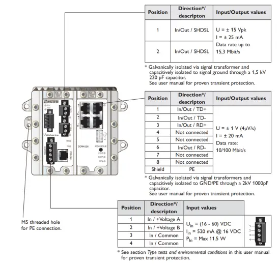
Interface specifications
| Power | |
| Rated voltage | 20 to 48 VDC |
| Operating voltage | 16 to 60 VDC |
| Rated current | 410 mA (575 mA) @ 20 VDC (with 500 mA USB load) 175 mA (240 mA) @ 48 VDC (with 500 mA USB load) |
| Rated frequency | DC |
| Inrush current, I2t | 1.5 A2s |
| Startup current* | 400 mA |
| Polarity | Reverse polarity protected |
| Redundant power input | Yes |
| Isolation to | All other |
| Connection | Detachable screw terminal |
| Connector size | 0.2 – 2.5 mm2 (AWG 24 – 12) |
| Shielded cable | Not required |
* External supply current capability for proper startup.
| Console | |
| Electrical specification | TTL-level |
| Data rate | 115.2 kbit/s |
| Data format | 8 data bits, none parity, 1 stop bit, no flow control |
| Circuit type | SELV |
| Isolation to | All other except USB |
| Galvanic connection to | USB |
| Connection | 2.5 mm jack, use Westermo cable 1211-2027 |
Connection to console port
The console port can be used to connect to the CLI (Command Line Interface).
The following steps needs to be taken
- Connect the serial diagnostic cable to the console port (use only Westermo cable 1211-2027).
- Connect cable to your computer (USB port, if drivers are needed they can be downloaded from our Web page).
- Use a terminal emulator and connect with correct speed and format to the assigned port.
For more information about the CLI, see the WeOS management guide.
| USB | |
| Electrical specification | USB 2.0 host interface |
| Data rate | Up to 12 Mbit/s (full-speed mode) |
| Circuit type | SELV |
| Maximum supply current | 500 mA |
| Isolation to | All other except Console |
| Galvanic connection to | Console |
| Connection | USB receptacle connector type A |
| Conductive housing | Yes |
| I/O / Relay output | |
| Connect resistance | 30 Ω |
| Isolation to | All other |
| Connection | Detachable screw terminal |
| Connector size | 0.2 – 2.5 mm2 (AWG 24 – 12) |
| Maximum voltage/current | 60 VDC / 80 mA |
| I/O / Digital input | |
| Voltage levels | Logic one >12V, Logic zero <1V |
| Isolation to | All other |
| Connection | Detachable screw terminal |
| Connector size | 0.2 – 2.5 mm2 (AWG 24 – 12) |
| Ethernet TX | |
| Electrical specification | IEEE std 802.3. 2005 Edition |
| Data rate | 10 Mbit/s or 100 Mbit/s, manual or auto |
| Duplex | Full or half, manual or auto |
| Circuit type | TNV-1 |
| Transmission range | Up to 150 m with CAT5e cable or better |
| Isolation to | All other |
| Connection | RJ-45 auto MDI/MDI-X |
| Shielded cable | Not required, except when installed in Railway applications as signalling and telecommunications apparatus and located close to rails.* |
| Conductive housing | Yes |
| Number of ports | 4 |
* To minimise the risk of interference, a shielded cable is recommended when the cable is located inside 3 m boundary or the cable is longer than 30 m and inside 10 m boundary to the rails and connected to this port.
| SHDSL | |
| Electrical specification | ITU-T G.991.2 Annex B |
| Data rate | 32 kbit/s to 15.3 Mbit/s |
| Protocol | EFM according to IEEE 802.3-2005 |
| Transmission range | According to ITU-T G.991.2 depending on line quality |
| Isolation to | All other |
| Connection | Detachable screw terminal |
| Connector size | 0.2 – 2.5 mm2 (AWG 24 – 12) |
| Shielded cable | Not required |
| Number of ports | 2 |
| RS-232 | |
| Electrical specification | EIA RS-232 |
| Data rate | 300 bit/s – 115.2 kbit/s |
| Data format | 7 or 8 data bits, odd/even/none parity, 1 or 2 stop bits |
| Protocol | Transparent, optimised by packing algorithm |
| Circuit type | SELV |
| Transmission range | 15 m / 49 ft |
| Isolation to | Power, DSL, Ethernet |
| Galvanic connection to | USB, Console |
| Connection | RJ-45 |
| Shielded cable | Not required |
| Conductive housing | Yes |
LED indicators
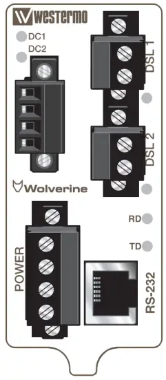
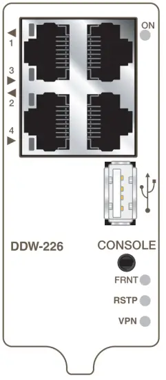
| LED | Status | Description |
| ON | OFF | Unit has no power. |
| GREEN | All OK, no alarm condition. | |
| RED | Alarm condition, or until unit has started up. (Alarm conditions are configurable, see ”WeOS Management Guide”). | |
| BLINK | Location indicator (“Here I am!”). Activated when connected to IPConfig Tool, or upon request from Web or CLI. | |
| DC1 | OFF | Unit has no power. |
| GREEN | Power OK on DC1. | |
| RED | Power failure on +DC1. | |
| DC2 | OFF | Unit has no power. |
| GREEN | Power OK on DC2. | |
| RED | Power failure on +DC2. | |
| FRNT | OFF | FRNT disabled. |
| GREEN | FRNT OK. | |
| RED | FRNT Error. | |
| BLINK | Unit configured as FRNT Focal Point. | |
| RSTP | OFF | RSTP disabled. |
| GREEN | RSTP enabled. | |
| BLINK | Unit elected as RSTP/STP root switch. | |
| VPN | OFF | VPN disabled. |
| GREEN | (Configurable) Default: At least one VPN tunnel up and OK. | |
| RED | (Configurable) Default: All VPN tunnels down. | |
| Copper ports Port 1-4 | OFF | No Link. |
| GREEN | Link established. | |
| GREEN FLASH | Data traffic indication. | |
| YELLOW | Port alarm and no link. Or if FRNT or RSTP mode, port is blocked. | |
| DSL ports Port 1-2 | OFF | No SHDSL link. |
| GREEN | SHDSL link established. | |
| GREEN BLINK | SHDSL link negotiation. | |
| GREEN FLASH | Data traffic indication. | |
| YELLOW | Port alarm and no link. Or if FRNT or RSTP mode, port is blocked. | |
| YELLOW BLINK | Only during unit startup. Firmware downloading to SHDSL chip. | |
| Serial port, RS-232 (DCE mode) | ||
| TD | OFF | No serial data received |
| GREEN FLASH | Serial data received | |
| RD | OFF | No serial data transmitted |
| GREEN FLASH | Serial data transmitted | |
Mounting
Mounting, 35 mm DIN-rail
The unit can be mounted on a 35 mm DIN-rail, which is horizontally mounted inside an apparatus cabinet, or similar. Snap on mounting.
Note! For proper vibration and chock performance Westermo recommends standard top-hat DIN-rail TH 35-15 according to EN 60715.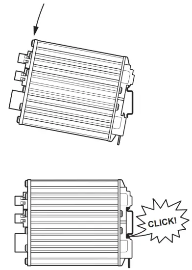
Removal
Press down the support at the back of the unit using a screwdriver.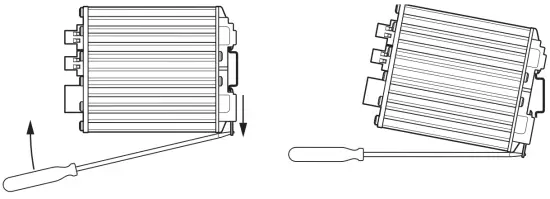
Wall mounting
This unit can also be wall-mounted.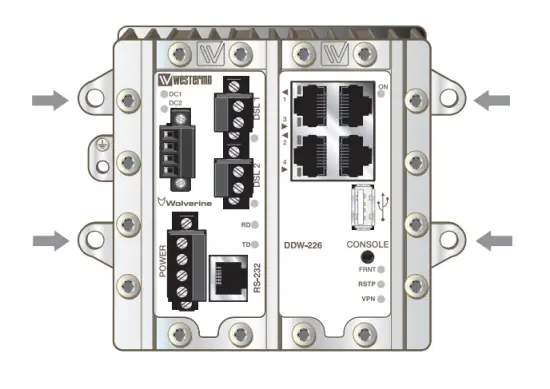
Earth connection
For correct function the ground connection on the unit needs to be properly connected to a solid ground.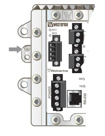
Cooling
This unit uses convection cooling. To avoid obstructing the airflow around the unit, use the following spacing rules. Minimum spacing 25 mm (1.0 inch) above /below and 10 mm (0.4 inches) left /right the unit. Spacing is recommended for the use of unit in full operating temperature range and service life.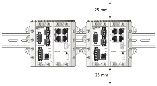
Getting Started
This product runs Westermo Operating System (WeOS) which provides several management tools that can be used for configuration of the unit.
- IPConfig tool
This is a custom Westermo tool used for discovery of attached Westermo units. - Web
Configuration of the unit using the web browser. - CLI
Configuration of the unit via the Command Line Interface.
If the computer is located in the same subnet as the switch you can easily use a web browser to configure the unit. Within the web you can configure most of the available functions.
For advanced network settings and more diagnostic information, please use the CLI. Detailed documentation is available in the chapter “The Command Line Management Tool” in the WeOS management guide.
Factory default
IP address: 192.168.2.200
Netmask: 255.255.255.0
Gateway: Disabled
Note! If you are not sure about the subnet – consult your network administrator.
Configuration
Configure the unit via web browser
The unit can easily be configured via a web browser. Open the link http://192.168.2.200 in your web browser, and you will be prompted with a Login screen, where the default settings for Username and Password are:
Username: admin
Password: westermo
Once you have logged in, you can use the extensive integrated help function describing all configuration options. Two common task when configuring a new switch is to assign appropriate IP settings, and to change the password of the admin account. The password can be up to 64 characters long, and should consist of printable ASCII characters (ASCII 33-126); ‘Space’ is not a valid password character.
Note! Version of IP Config tool must be 10.3.0 or higher.
Referring documents
| Type | Description | Document number |
| Management Guide | Westermo OS management guide | 6101-3201 |
Factory default on DDW-226
It is possible to set the unit to factory default settings by using two standard Ethernet RJ-45 cables.
- Power off the switch and disconnect all Ethernet cables and DSL cables.
- Connect one Ethernet cable between Ethernet port 1 and Ethernet port 4, and another Ethernet cable between Ethernet port 2 and Ethernet port
- The ports need to be connected directly by Ethernet cables, i.e., not via a hub or switch. Use straight cables – not cross-over cables – when connecting the port pairs.
- Power on the unit.
- Wait for the unit to start up. Control that the ON LED is flashing red. The ON LED flashing indicates that the unit is now ready to be reset to factory default. You now have the choice to go ahead with the factory reset, or to skip factory reset and boot as normal.
• Go ahead with factory reset:
Acknowledge that you wish to conduct the factory reset by unplugging one of the Ethernet cables. The ON LED will stop flashing. This initiates the factory reset process*, and after approximately 1 minute the unit will restart with factory default settings. When the switch has booted up, the ON LED will typically show a green light (a red light is shown if only one of the DC power feeds is connected).
• Skip the factory reset:
To skip the factory reset process, just wait for approximately 30 seconds (after the ON LED starts flashing RED) without unplugging any of the Ethernet cables. The switch will conduct a normal boot with the existing settings.
* Note Do not power off the unit while the factory reset process is in progress.

· Metallverksgatan 6, SE-721 30 Västerås, Sweden
Tel +46 16 42 80 00 Fax +46 16 42 80 01
E-mail: [email protected]
www.westermo.com
REV. K 6642-22402 2021-12 Westermo Network Technologies AB, Sweden


