kramer EXT3-XR-TR DMI Extender with USB Ethernet
Product Information
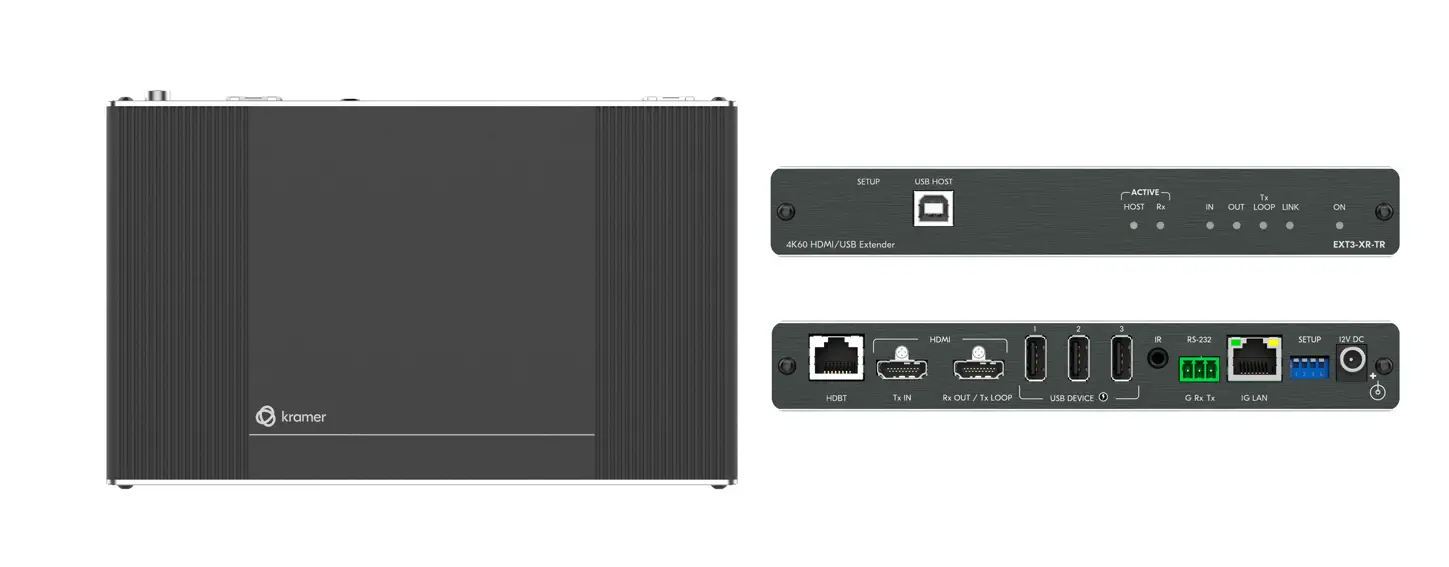
| Product Name | EXT3-XR-TR 4K60 HDMI/USB Extender |
|---|---|
| Manufacturer | Kramer Electronics Ltd. |
| Product Features | The EXT3-XR-TR is a versatile HDMI/USB extender device that can function as a transmitter or a receiver. It supports 4K60 resolution and allows for the extension of HDMI and USB signals over long distances. The device also features HDBT Range Mode for different range settings, USB connectivity for peripheral devices, LED indicators for status monitoring, multiple connectors for various inputs and outputs, and support for IR and RS-232 control. |
Product Usage Instructions
Step 1: Check what’s in the box
- EXT3-XR-TR 4K60 HDMI/USB Extender
- 1 Power adapter and cord
- 1 Bracket set
- 4 Rubber feet
- 1 Quick start guide
Step 2: Get to know your EXT3-XR-TR
| Feature | Function |
|---|---|
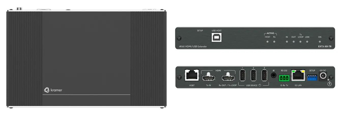
| 1 | SETUP 2-way DIP-switch |
| 2 | HOST USB B 2.0 Connector |
| 3 | ACTIVE HOST LED |
| 4 | ACTIVE Rx LED |
| 5 | IN LED |
| 6 | OUT LED |
| 7 | TX LOOP |
| 8 | LINK LED |
| 9 | ON LED |
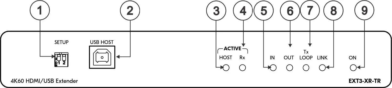
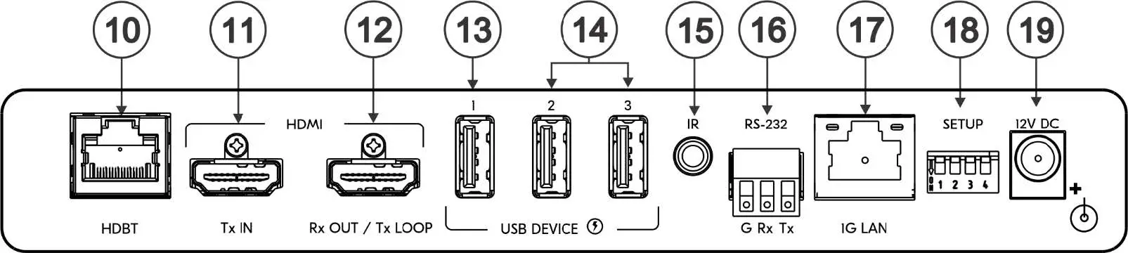
| 10 | HDBT RJ-45 Connector |
| 11 | HDMI TX IN Connector |
| 12 | HDMI Rx OUT/Tx LOOP Connector |
| 13 | USB A 2.0 Connector 1 |
| 14 | USB A 2.0 Connectors 2-3 |
| 15 | IR 3.5mm Mini Jack Connector |
| 16 | RS-232 3-pin Terminal Block |
| 17 | ETHERNET RJ-45 Connector |
| 18 | SETUP 4-way DIP-switch |
| 19 | 12V DC Power Connector |
Step 3: Download the full user manual and check for firmware upgrades
Go to www.kramerav.com/downloads/EXT3-XR-TR
to download the latest user manual and check if firmware upgrades are available.
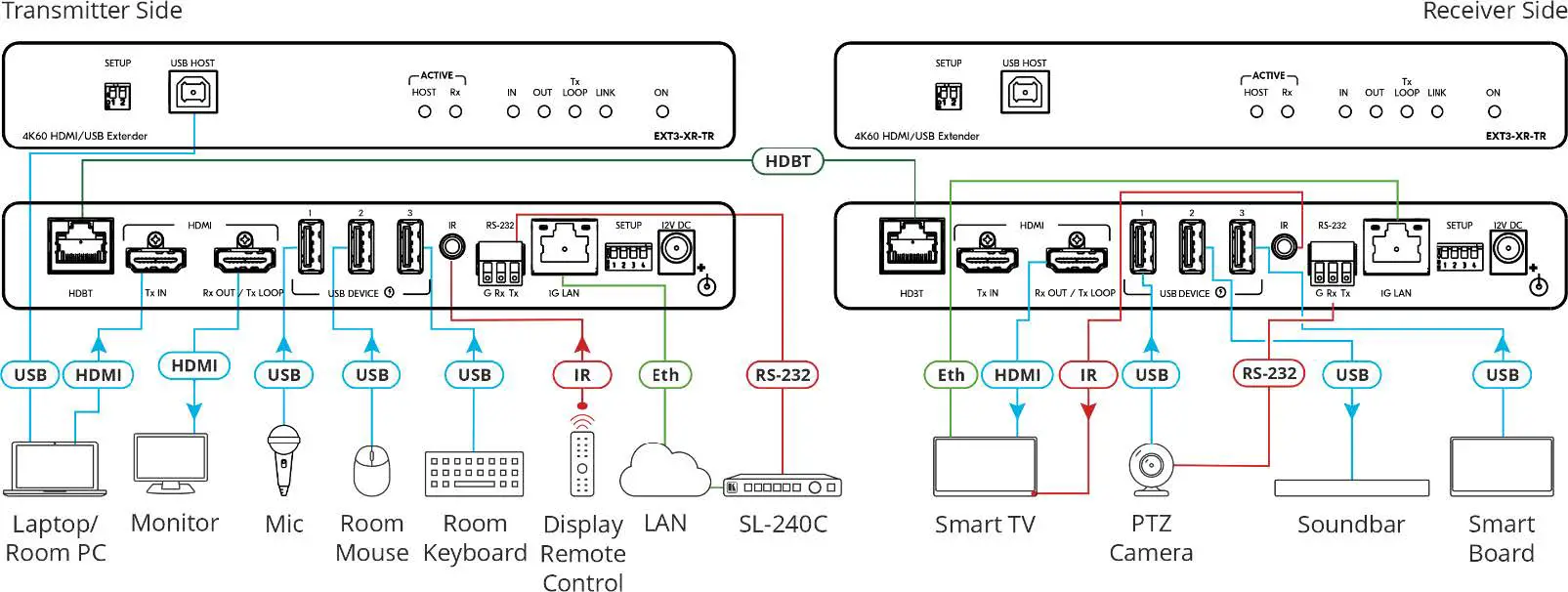
Step 4: Connect inputs and outputs
- Connect the HDBT RJ-45 connector on a paired receiver/transmitter device to the HDBT RJ-45 connector on the EXT3-XR-TR.
- In transmitter mode, connect an HDMI source to the HDMI TX IN connector.
- In receiver mode, connect an HDMI acceptor to the HDMI Rx OUT/Tx LOOP connector.
- Connect USB peripheral devices to the USB connectors depending on their type and purpose.
- If required, connect an external IR emitter or IR sensor to the IR 3.5mm Mini Jack Connector for IR control.
- If required, connect a controller device to the RS-232 3-pin Terminal Block for remote device control via serial connection.
- Connect to the LAN using the ETHERNET RJ-45 Connector.
- Set the desired device behavior using the SETUP DIP-switches.
- Finally, connect the power supply to the 12V DC Power Connector.
 Scan for full manual
EXT3-XR-TR Quick Start Guide
This guide helps you install and use your EXT3-XR-TR for the first time.
Go to www.kramerav.com/downloads/EXT3-XR-TR to download the latest user manual and check if firmware upgrades are available.
Step 1: Check what’s in the box
- EXT3-XR-TR 4K60 HDMI/USB Extender
- 1 Power adapter and cord
- 1 Bracket set
- 4 Rubber feet
- 1 Quick start guide
Step 2: Get to know your EXT3-XR-TR
The extender device functions as a transmitter or a receiver side per DIP-switch setting (see Step 4:Connect inputs and outputs).
| # | Feature | Function | |||
| 1 | SETUP 2-way DIP-switch | Set the HDBT Range Mode. | |||
| DIP 1 | DIP 2 | State Description | |||
| Off (up) | Off (up) | Standard range mode. | |||
| Off (up) | On (down) | Ultra-long range mode. | |||
| On (down) | Off (up) | TBD | |||
| On (down) | On (down) | TBD | |||
| 2 | HOST USB B 2.0 Connector | Connect to the USB host (for example, a laptop) to communicate with the USB peripheral devices (for example, a smart board) connected to USB device ports on either the transmitter or the receiver sides of the extender (see Step 4:Connect inputs and outputs). | |||
| 3 | ACTIVE HOST LED | Lights orange when the USB host side is active | |||
| 4 | ACTIVE Rx LED | Lights green when the extender receiver function is active | |||
| 5 | IN LED | Lights blue when an active HDMI input signal is detected on HDMI IN. | |||
| 6 | OUT LED | Lights blue when an output acceptor device is connected. | |||
| 7 | TX LOOP | Transmitter mode | Lights blue an active signal is transmitted on the Tx LOOP port. | ||
| Receiver mode | N/A | ||||
| 8 | LINK LED | Lights green when the HDBT active link connection is established. | |||
| 9 | ON LED | Lights green when the device receives power. | |||
| # | Feature | Function | |
| 10 | HDBT RJ-45 Connector | Connect to the HDBT RJ-45 connector on a paired receiver/transmitter device (for example, a second EXT3-XR-TR device). | |
| 11 | HDMI TX IN Connector | Transmitter mode | Connect to an HDMI source. |
| Receiver Mode | N/A | ||
| 12 | HDMI Rx OUT/Tx LOOP Connector | Transmitter mode | Connect to a local acceptor. |
| Receiver mode | Connect to an HDMI acceptor. | ||
| 13 | USB A 2.0 Connector 1 | Connect to the USB local peripheral devices (for example, a USB PTZ camera). When USB Host PC is disconnected, the USB signal and charging power for this port are inactive. | |
| 14 | USB A 2.0 Connectors 2-3 | Connect to the USB local peripheral devices (for example, a USB camera, a soundbar, microphone and so on). When USB Host PC is disconnected, the USB charging power for this port continues to be active. | |
| 15 | IR 3.5mm Mini Jack Connector | Connect to an external IR emitter to control a local IR-controlled device from the remote extender (for example, EXT3-XR-TR). Connect to an IR sensor to control a remote IR-controlled device connected to the remote extender side (for example, EXT3-XR-TR). | |
| 16 | RS-232 3-pin Terminal Block | Connect to a controller device (for example, SL-240C) to control a remote device via serial connection (for example, the remotely connected PTZ USB camera). | |
| 17 | ETHERNET RJ-45 Connector | Connect to LAN. | |
| 18 | SETUP 4-way DIP-switch | Sets the device behavior (see Step 4:Connect inputs and outputs). | |
| 19 | 12V DC Power Connector | Connect to the power supply. | |
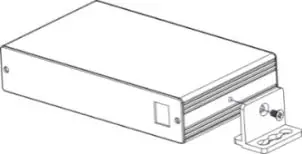
Step 3: Mount EXT3-XR-TR
Install EXT3-XR-TR using one of the following methods:
- Attach the rubber feet and place the unit on a flat surface.
- Fasten a bracket (included) on each side of the unit and attach it to a flat surface (see www.kramerav.com/downloads/EXT3 XR TR).
- Mount the unit in a rack using the recommended rack adapter (see www.kramerav.com/product/EXT3 XR TR).
- Ensure that the environment (e.g., maximum ambient temperature & air flow) is compatible for the device.
- Avoid uneven mechanical loading.
- Appropriate consideration of equipment nameplate ratings should be used for avoiding overloading of the circuits.
- Reliable earthing of rack-mounted equipment should be maintained.
- Maximum mounting height for the device is 2 meters.
Step 4: Connect inputs and outputs
Always switch OFF the power on each device before connecting it to your EXT3-XR-TR extender.
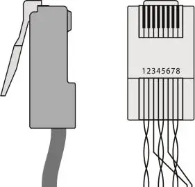
Wiring the RJ-45 Connectors
This section defines the HDBT pinout, using a straight pin-to-pin cable with RJ-45 connectors.
For HDBT cables, it is recommended that the cable ground shielding be connected/soldered to the connector shield.
To achieve specified extension distances, use the recommended Kramer cables available at www.kramerav.com/product/EXT3 XR TR. Using third-party cables may cause damage!
| EIA /TIA 568B | |
| PIN Wire Color | |
| 1 | Orange / White |
| 2 | Orange |
| 3 | Green / White |
| 4 | Blue |
| 5 | Blue / White |
| 6 | Green |
| 7 | Brown / White |
| 8 | Brown |
Setting the DIP Switches
- All DIP-switches are set to OFF (up) by default
- All changes in DIP-Switches apply immediately, on-the-fly (no need to power cycle the device), except for DIP-switches 1 and 2.
| # | Feature | DIP-switch Settings | 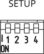 |
| 1 | Device Operation Mode | OFF (up) – Receiver mode is active. ON (down) – Transmitter mode is active. | |
| 2 | Active USB Host port | OFF (up) – Host is active. ON (down) – Host is inactive (active on remote paired device). | |
| 3 | Define IR Pass-through | OFF (up) – Pass-through the IR signal to or from the IR cable. ON (down) – Add IR modulation (38kHz) to the IR output signal (applies only when the IR port is connected to an IR emitter cable). | |
| 4 | Programing RS-232 | Off (up) – Normal operation mode is enabled (FW programming RS-232 is inactive). On (down) – FW programming RS-232 is active. | |
Step 5: Connect power
Connect the power cord to EXT3-XR-TR and plug it into the mains electricity.
Safety Instructions (See www.kramerav.com for updated safety information) Caution:
- For products with relay terminals and GPI\O ports, please refer to the permitted rating for an external connection, located next to the terminal or in the User Manual.
- There are no operator serviceable parts inside the unit.
Warning:
- Use only the power cord that is supplied with the unit.
- Disconnect the power and unplug the unit from the wall before installing.
Step 6: Operate EXT3-XR-TR
When connecting USB devices to the USB ports, note that
- The recommended connected USB hub capacity is ≤6.
- The maximum connected USB hub capacity is ≤15.
We recommend that you use USB host PC tools, such as USB TreeView tool, to verify connected USB hubs (internal and externals) and endpoints capacity.


