![]() TP-600TRxr Quick Start Guide
TP-600TRxr Quick Start Guide
This guide helps you install and use your TP-600TRxr for the first time.
Go to www.kramerav.com/downloads/TP-600TRxr to download the latest user manual and check if the firmware upgrades are available.
Scan for full manual

https://de2gu.app.goo.gl/bWUz1PaQzjQaqWQg8
Step 1: Check what’s in the box
- TP-600TRxr 4K60 HDMI/USB Extender
- 1 Power adapter and cord
- 1 Set of rack ears
- 1 Bracket set
- 4 Rubber feet
- 1 Quick start guide
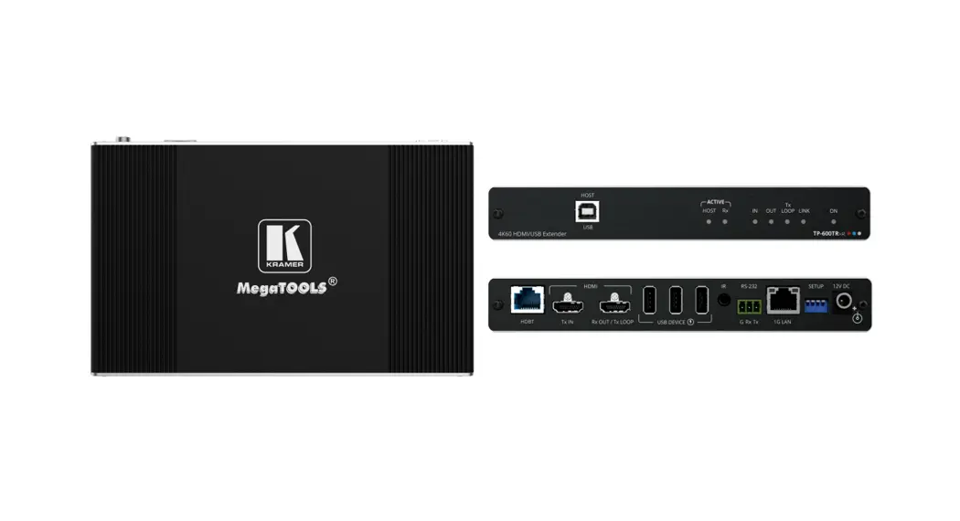
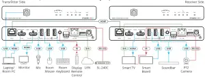
Step 2: Get to know your TP-600TRxr
The extender device functions as a transmitter or a receiver side per the DIP-switch setting (see Step 4:Connect inputs and outputs).
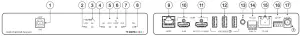
| # | Feature | Function | |
| 1 | HOST USB B 2.0 Connector | Connect to the USB peripheral devices (for either the transmitter inputs and outputs).host (for example, a laptop) to communicate with the USB example, a smartboard) connected to USB device ports on or the receiver sides of the extender (see Step 4:Connect | |
| 2 | ACTIVE HOST LED | Lights orange when the USB host side is active | |
| 3 | ACTIVE Rx LED | Lights green when the extender receiver function is active | |
| 4 | IN LED | Lights blue when an active HDMI input signal is detected on HDMI IN. | |
| 5 | OUT LED | Lights blue when an output acceptor device is connected. | |
| 6 | TX LOOP | Transmitter mode | Lights blue an active signal is transmitted on the Tx LOOP port. |
| Receiver mode | N/A | ||
| 7 | LINK LED | Lights green when the HDBT active link connection is established. | |
| 8 | ON LED | Lights green when the device receives power. | |
| 9 | HDBT RJ-45 Connector | Connect to the HDBT RJ-45 connector on a paired receiver/transmitter device (for example, a second TP-600TRxr device). | |
| 10 | HDMI TX IN Connector | Transmitter mode | Connect to an HDMI source. |
| Receiver Mode | N/A | ||
| 11 | HDMI Rx OUT/Tx LOOP Connector | Transmitter mode | Connect to a local acceptor. |
| Receiver mode | Connect to an HDMI acceptor. | ||
| 12 | USB A 2.0 Fast-Charging Connectors (3) | Connect to the USB local peripheral devices (for example, a USB camera, a soundbar, microphone, and so on). | |
| 13 | IR 3.5mm Mini-Jack Connector | Connect to an external IR emitter to control a local IR-controlled device from the remote extender (for example, TP-600TRxr). Connect to an IR sensor to control a remote IR-controlled device connected to the remote extender side (for example, TP-600TRxr). | |
| 14 | RS-232 3-pin Terminal Block | Connect to a controller device (for example, SL240C) to control a remote device via serial connection (for example, the remotely connected PTZ USB camera). | |
| 15 | ETHERNET RJ-45 Connector | Connect to LAN. | |
| 16 | SETUP 4-way DIP-switch | Sets the device behavior (see Step 4:Connect inputs and outputs). | |
| 17 | 12V DC Power Connector | Connect to the power supply. | |
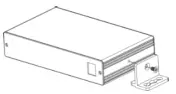
Step 3: Mount TP-600TRxr
Install TP-600TRxr using one of the following methods:
- Attach the rubber feet and place the unit on a flat surface.
- Fasten a bracket (included) on each side of the unit and attach it to a flat surface (see www.kramerav.com/downloads/TP-600TRxr).
- Mount the unit in a rack using the recommended rack adapter (see www.kramerav.com/product/TP-600TRxr).

- Ensure that the environment (e.g., maximum ambient temperature & airflow) is compatible with the device.
- Avoid uneven mechanical loading.
- Appropriate consideration of equipment nameplate ratings should be used for avoiding the overloading of the circuits.
- Reliable earthing of rack-mounted equipment should be maintained.
- The maximum mounting height for the device is 2 meters.
Step 4: Connect inputs and outputs
Always switch OFF the power on each device before connecting it to your TP-600TRxr extender.
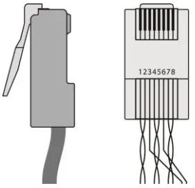
Wiring the RJ-45 Connectors
This section defines the HDBT pinout, using a straight pin-to-pin cable with RJ-45 connectors.
 For HDBT cables, it is recommended that the cable ground shielding be connected/soldered to the connector shield.To achieve specified extension distances, use the recommended Kramer cables available at www.kramerav.com/product/TP600TRxr.Using third-party cables may cause damage!
| EIA /TIA 568B | |
| PIN | Wire Color |
| 1 | Orange / White |
| 2 | Orange |
| 3 | Green / White |
| 4 | Blue |
| 5 | Blue / White |
| 6 | Green |
| 7 | Brown / White |
| 8 | Brown |
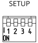
Setting the DIP Switches
- All DIP-switches are set to OFF (up) by default
- All changes in DIP-Switches apply immediately, on the fly (no need to power cycle the device), except for DIP-switches 1 and 2.

| # | Feature | DIP-switch Settings | |
| 1 | Device Operation Mode | OFF (up) — Receiver mode is active. ON (down) — Transmitter mode is active. | |
| 2 | Active USB Host port | OFF (up) — Host is active. ON (down) — Host is inactive (active on remote paired device). | |
| 3 | Define IR Pass-through | OFF (up) — Pass through the IR signal to or from the IR cable. ON (down) — Add IR modulation (38kHz) to the IR output signal (applies only when the IR port is connected to an IR emitter cable). | |
| 4 | Programing RS-232 | Off (up) — Normal operation mode is enabled (FW programming RS-232 is inactive). On (down) — FW programming RS-232 is active. | |
Step 5: Connect power
Connect the power cord to TP-600TRxr and plug it into the mains electricity.Safety Instructions (See www.kramerav.com for updated safety information)
Caution:
- For products with relay terminals and GPI\O ports, please refer to the permitted rating for an external connection, located next to the terminal or in the User Manual.
- There are no operator serviceable parts inside the unit.
Warning:
- Use only the power cord that is supplied with the unit.
- Disconnect the power and unplug the unit from the wall before installing.