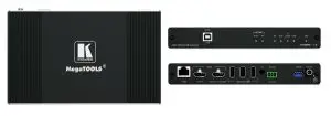
KRAMER TP-600TR HDMI Extender with USB
 | TP-600TR Quick Start Guide This guide helps you install and use your TP-600TR for the first time. Go to www.kramerav.com/downloads/TP-600TR to download the latest user manual and check if firmware upgrades are available. |
Step 1: Check what’s in the box
- TP-600TR 4K60 HDMI/USB Extender
- 1 Power adapter and cord
- 1 Bracket set
- 4 Rubber feet
- 1 Quick start guide
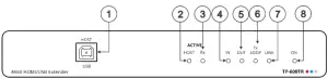
Step 2: Get to know your TP-600TR
The extender device functions as a transmitter or a receiver side per DIP-switch setting (see Step 4:Connect inputs and outputs).
| # | Feature | Function | |
| 1 | HOST USB B 2.0 Connector | Connect to the USB host (for example, a laptop) to communicate with the USB peripheral devices (for example, a smart board) connected to USB device ports on either the transmitter or the receiver sides of the extender (see Step 4:Connect inputs and outputs). | |
| 2 | ACTIVE HOST LED | Lights orange when the USB host side is active | |
| 3 | ACTIVE Rx LED | Lights green when the extender receiver function is active | |
| 4 | IN LED | Lights blue when an active HDMI input signal is detected on HDMI IN. | |
| 5 | OUT LED | Lights blue when an output acceptor device is connected. | |
| 6 | TX LOOP | Transmitter mode | Lights blue an active signal is transmitted on the Tx LOOP port. |
| Receiver mode | N/A | ||
| 7 | LINK LED | Lights green when the HDBT active link connection is established. | |
| 8 | ON LED | Lights green when the device receives power. | |
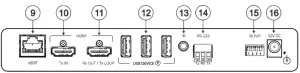
| 9 | HDBT RJ-45 Connector | Connect to the HDBT RJ-45 connector on a paired receiver/transmitter device (for example, a second TP-600TR device). | |
| 10 | HDMI TX IN Connector | Transmitter mode | Connect to an HDMI source. |
| Receiver Mode | N/A | ||
| 11 | HDMI Rx OUT/Tx LOOP Connector | Transmitter mode | Connect to a local acceptor. |
| Receiver mode | Connect to an HDMI acceptor. | ||
| 12 | USB A 2.0 Fast-Charging Connectors (3) | Connect to the USB local peripheral devices (for example, a USB camera, a soundbar, microphone and so on). | |
| 13 | IR 3.5mm Mini Jack Connector | Connect to an external IR emitter to control a local IR-controlled device from the remote extender (for example, TP-600TR). Connect to an IR sensor to control a remote IR-controlled device connected to the remote extender side (for example, TP-600TR). | |
| 14 | RS-232 3-pin Terminal Block | Connect to a controller device (for example, SL240C) to control a remote device via serial connection (for example, the remotely connected PTZ USB camera). | |
| 15 | SETUP 4-way DIP-switch | Sets the device behavior (see Step 4:Connect inputs and outputs). | |
| 16 | 12V DC Power Connector | Connect to the power supply. | |
The terms HDMI, HDMI High-Definition Multimedia Interface, and the HDMI Logo are trademarks or registered trademarks of HDMI Licensing Administrator, Inc.
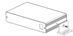
Step 3: Mount TP-600TR
Install TP-600TR using one of the following methods:
- Attach the rubber feet and place the unit on a flat surface.
- Fasten a bracket (included) on each side of the unit and attach it to a flat surface (see www.kramerav.com/downloads/TP-600TR).
- Mount the unit in a rack using the recommended rack adapter (see www.kramerav.com/product/TP-600TR).
 |
|
Step 4: Connect inputs and outputs
Always switch OFF the power on each device before connecting it to your TP 600TR extender.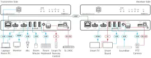
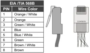
Wiring the RJ-45 Connectors
This section defines the HDBT pinout, using a straight pin-to-pin cable with RJ-45 connectors.
 | For HDBT cables, it is recommended that the cable ground shielding be connected/soldered to the connector shield. |
| To achieve specified extension distances, use the recommended Kramer cables available at www.kramerav.com/product/TP600TR. Using third-party cables may cause damage! |
Setting the DIP Switches
- All DIP-switches are set to OFF (up) by default
- All changes in DIP-Switches apply immediately, on-the-fly (no need to power cycle the device), except for DIP-switches 1 and 2.
| # | Feature | DIP-switch Settings | 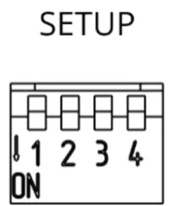 |
| 1 | Device Operation Mode | OFF (up) – Receiver mode is active. ON (down) – Transmitter mode is active. | |
| 2 | Active USB Host port | OFF (up) – Host is active. ON (down) – Host is inactive (active on remote paired device). | |
| 3 | Define IR Pass-through | OFF (up) – Pass-through the IR signal to or from the IR cable. ON (down) – Add IR modulation (38kHz) to the IR output signal (applies only when the IR port is connected to an IR emitter cable). | |
| 4 | Programing RS-232 | Off (up) – Normal operation mode is enabled (FW programming RS-232 is inactive). On (down) – FW programming RS-232 is active. | |
Step 5: Connect power
Connect the power cord to TP-600TR and plug it into the mains electricity.
| Safety Instructions (See www.kramerav.com for updated safety information) Caution:
Warning:
|