![]()
USER GUIDE
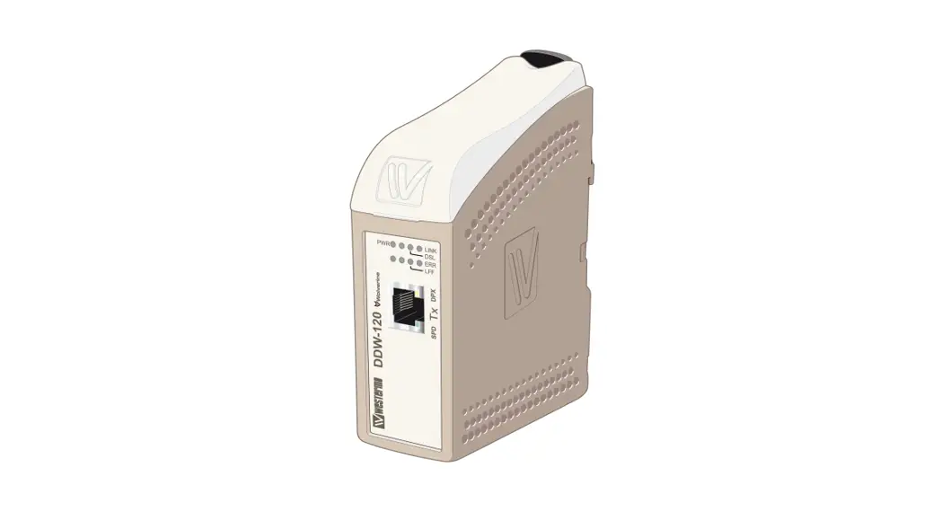
Wolverine DDW-120
Industrial Ethernet SHDSL Extender
General information
Legal information
The contents of this document are provided “as is”. Except as required by applicable law, no warranties of any kind, either express or implied, including, but not limited to, the implied warranties of merchantability and fitness for a particular purpose, are made in relation to the accuracy and reliability or contents of this document. Westermo reserves the right to revise this document or withdraw it at any time without prior notice.
Under no circumstances shall Westermo be responsible for any loss of data or income or any special, incidental, consequential, or indirect damages howsoever caused.
More information about Westermo can be found at www.westermo.com
Software tools
Related software tools are available in the folder software tools under technical support on the Westermo website.
Safety and Regulations
Warning signs are provided to prevent personal injuries and/or damages to the product.
The following levels are used:
| Level of warning | Description | Consequence personal injury | Consequence material damage |
| Indicates a potentially hazardous situation | Possible death or major injury | Major damage to the product |
| Indicates a potentially hazardous situation | Minor or moderate injury | Moderate damage to the product |
| Provides information in order to avoid misuse of the product, confusion, or misunderstanding | No personal injury | Minor damage to the product |
| Used for highlighting general, but important information | No personal injury | Minor damage to the product |
 NOTICE
 NOTE
NOTEBefore installation:
Read this manual completely and gather all information on the product. Make sure that you understand it fully. Check that your application does not exceed the safe operating
specifications for this product.
SAFETY DURING INSTALLATION The product must be installed by qualified service personnel and built into an apparatus cabinet or similar, where access is restricted to service personnel only.
During installation, ensure a protective earthing conductor is first connected to the protective earthing terminal (only valid for metallic housings). Westermo recommends a cross-sectional area of at least 4 mm2.
If the product does not have a protective earthing terminal, then the DIN-rail must be connected to the protective earth. Upon removal of the product, ensure that the protective earthing conductor, or the connection to earth via the DIN-rail, is disconnected last.
HAZARDOUS VOLTAGEDo not open an energized product. Hazardous voltage may occur when connected to a power supply.
PROTECTIVE FUSE It must be possible to disconnect manually from the power supply. Ensure compliance with national installation regulations. Replacing the internal fuse must only be performed by Westermo qualified personnel.
REDUCE THE RISK OF FIRETo reduce the risk of fire, use only telecommunication line cords with a cable diameter of AWG 26 or larger. Regarding power cable dimensions, see Interface Specifications.
ELECTROSTATIC DISCHARGE (ESD) Prevent electrostatic discharge damage to internal electronic parts by discharging your body to a grounding point (e.g. use a wrist strap).
Care recommendations
Follow the care recommendations below to maintain the full operation of the product and fulfill the warranty obligations:
- Do not drop, knock or shake the product. Rough handling above the specification may cause damage to internal circuit boards.
- Use a dry or slightly water-damp cloth to clean the product. Do not use harsh chemicals, cleaning solvents, or strong detergents.
- Do not paint the product. Paint can clog the product and prevent proper operation.
If the product is used in a manner not according to specification, the protection provided by the equipment may be impaired.
If the product is not working properly, contact the place of purchase, nearest Westermo distributor office, or Westermo technical support.
Product disposal
 This symbol means that the product shall not be treated as unsorted municipal waste when disposed of it. It needs to be handed over to an applicable collection point for recycling electrical and electronic equipment.
By ensuring this product is disposed of correctly, you will help to reduce hazardous substances and prevent potential negative consequences to both environment and human health, which could be caused by inappropriate disposal.
Simplified EU declaration of conformity
Hereby, Westermo declares that this product is in compliance with applicable EU directives and UK legislation. The full declaration of conformity and other detailed information is available at www.westermo.com/support/product-support

![]()
Agency approvals and standards compliance
| Type | Approval / Compliance |
| EN 61000-6-2, Immunity industrial environments | |
| EN 61000-6-4, Emission standard for industrial environments | |
| EN 50121-4, Railway signaling and telecommunications apparatus | |
| Safety | UL 60950-1, IT equipment |
| SHDSL | ITU-T G.991.2, G.SHDSL and G.SHDSL.bis standard |
| Environmental | NEMA TS 2-2003 version 02.06 Traffic Controller Assemblies with NTCIP Requirements |
FCC Part 15.105 Notice:
This equipment has been tested and found to comply with the limits for a Class B digital device, pursuant to Part 15 of the FCC Rules. These limits are designed to provide reasonable protection against harmful interference in a residential installation. This equipment generates, uses, and can radiate radio frequency energy and, if not installed and used in accordance with the instructions, may cause harmful interference to radio communications. However, there is no guarantee that interference will not occur in a particular installation. If this equipment does cause harmful interference to radio or television reception, which can be determined by turning the equipment off and on, the user is encouraged to try to correct the interference by one or more of the following measures:![]() Reorient or relocate the receiving antenna
Reorient or relocate the receiving antenna![]() Increase the separation between the equipment and receiver
Increase the separation between the equipment and receiver![]() Connect the equipment into an outlet on a circuit different from that to which the receiver is connected
Connect the equipment into an outlet on a circuit different from that to which the receiver is connected![]() Consult the dealer or an experienced radio/TV technician for help.
Consult the dealer or an experienced radio/TV technician for help.
Type tests and environmental conditions
| Phenomena | Test | Description | Test levels |
| ED | EN 61000-4-2 | Enclosure contact | ± 6 kV |
| Enclosure air | ± 8 kV | ||
| RF field AM modulated | IEC 61000-4-3 | Enclosure | 20 V/m 80% AM (1 kHz), 80 – 2 000 MHz 10 V/m 80% AM (1 kHz), 2 000 – 6 000 MHz |
| RF field 900 MHz | ENV 50204 | Enclosure | 20 V/m pulse-modulated 200 Hz, 900 ± 5 MHz |
| Fast transient | EN 61000-4-4 | Signal ports | ± 2 kV |
| Power ports | ± 2 kV | ||
| Surge | EN 61000-4-5 | Signal ports unbalanced | ± 2 kV line to earth, ± 2 kV line to line |
| Signal ports balanced | ± 2 kV line to earth, ± 1 kV line to line | ||
| Power ports | ± 2 kV line to earth, ± 2 kV line to line | ||
| RF conducted | EN 61000-4-6 | Signal ports | 10 V 80% AM (1 kHz), 0.15 – 80 MHz |
| Power ports | 10 V 80% AM (1 kHz), 0.15 – 80 MHz | ||
| Power frequency magnetic field | EN 61000-4-8 | Enclosure | 100 A/m, 50 Hz, 16.7 Hz & 0 Hz |
| Pulse magnetic field | EN 61000-4-9 | Enclosure | 300 A/m, 6.4 / 16 µs pulse |
| Mains freq. 50 Hz | EN 61000-4-16 | Signal ports | 100 V 50 Hz line to earth |
| Mains freq. 50 Hz | SS 436 15 03 | Signal ports | 250 V 50 Hz line to earth |
| Radiated emission | EN 61000-6-4 | Enclosure | EN 61000-6-4, up to 6 GHz |
| Conducted emission | CISPR 16-2-1 | DC power ports | EN 61000-6-4 |
| Dielectric strength | UL 60950-1 | Signal port to other isolated ports | 2 Vrms 50 Hz 1 min |
| Power port to other isolated ports | 3 Vrms 50 Hz 1 min 2 Vrms 50 Hz 1 min (@ rated power <60 V) | ||
| Temperature | EN 60068-2-1 EN 60068-2-2 | Operating | –40 to +70ºC |
| Storage & Transport | –40 to +70ºC | ||
| Humidity | EN 60068-2-30 | Operating | 5 to 95% relative humidity |
| Storage & Transport | 5 to 95% relative humidity | ||
| Altitude | Operating | 2 000 m / 70 kPa | |
| Reliability prediction (MTBF) | MIL-HDBK- 217F | Operating | 1 180 000 hours |
| Service life | Operating | 10 years | |
| Vibration | IEC 60068-2-6 | Operating | 7.5 mm, 5 – 8 Hz 2 g, 8 – 500 Hz |
| Shock | IEC 60068-2-27 | Operating | 15 g, 11 ms |
| Enclosure | UL 94 | PC / ABS | Flammability class V-1 |
| Dimension W x H x D | 35 x 121 x 119 mm | ||
| Weight | 0.2 kg | ||
| Degree of protection | IEC 529 | Enclosure | IP21 |
| Cooling | Convection | ||
| Mounting | Horizontal on 35 mm DIN-rail |
Description
Functional description
The DDW-120 Ethernet Extender is the ideal solution for extending your Ethernet network over copper cables where in the past the only option would have been fiber.
At a shorter range, the transfer rate will be as fast as 15.3 Mbit/s in both directions.
Depending on the quality of the cables distances up to 15 km are possible.
DDW-120 is transparent for multicast addressing, VLAN packets, VPN pass-through for IPSec, and for protocols like MODBUS/TCP and Profinet. The Link Fault Forward LFF) functionality in DDW-120 forwards information about the Ethernet link status, this is sent over the SHDSL link between two DDW-120 units. In many applications, it is a requirement to disconnect the link on the other side of the SHDSL link if the primary Ethernet link goes down.
The units will auto-negotiate the transmission speed but can also be forced to choose a slower (more reliable) or faster (less reliable) data rate.
Communication speed and distance depend on the cable characteristics, communication reach with different cables can be calculated with DDW-tool
DDW-120 has dual power input in case power supply redundancy is needed. In case only one power source is connected the unit will still operate according to specification.
DDW-120 can be used in point-to-point applications or as a start and termination unit together with other Wolverine products in daisy-chain applications.
Description of used nomenclature:
Noise margin:
The margin between signal and noise (dB)
CO/CPE:
CO (Central Office) answering central unit, the CO configures the CPE when establishing a connection. CPE (Customer Premises Equipment) is the unit that initiates the connection.
Getting started
The DDW-120 is easy to use and install, the units work in pairs, one has to be configured as CO (Central Office) and one as CPE (Customer Premises Equipment). This configuration is made with DIP switches situated under the lid of the DDW-120.
- Connect the SHDSL Line
1) Connect the twisted pair to DSL screw terminals 1 and 2 (polarity independent) situated at the base of the DDW-120. - Connect the Ethernet Line
Connect Ethernet to the TX port on the front of the DDW-120.
The factory settings for the DDW-120 is plug and play mode where the TX port is enabled for: Ethernet Auto-negotiation enabled.Auto MDI/MDI-X.Auto-polarity enabled.
The DDW-120 will automatically sense the data rate of the connected unit and cable type. - Settings in the units
The units operate in pairs, one as CO (Central Office) and one as CPE (Customer Premises Equipment). Factory setting in the DDW-120 is as CPE.
Note! Before connection and installation, one of the connecting units has to be reconfigured as a CO, see DIP-switch S1:4.
Depending on the quality of the line and the distance there is the possibility to select the autobaud function.
This is done via DIP switches in the unit configured as CO. Factory default is autobaud, reliable mode.
Note! If the DSL link is not established, the speed might be set too high for the distance.
Diagnostic information
The DDW-120 can display diagnostic information in two ways:
1) Using the Westermo diagnostic tool DDWtool.exe.
2) Using a terminal program.
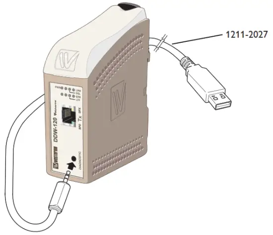
Using DDW-tool
1) Connect the standard cable 1211-2027 to the diagnostic port, located under the lid of DDW-120.
2) Choose the corresponding Com port in the drop list of the tool. The tool will try to find the port used by the debug cable.
3) Click the button connect, if the correct com port is selected DDW-tool will be updated with actual status online information.
Information from the diagnostic tool
- Software release
- Serial number
- DIP switch settings
- If the unit is configured as CO or CPE
- Ethernet link status
- Ethernet data rate
- Ethernet duplex
- System uptime
- DSL uptime
- DSL negotiations
- LFF status
- DSL link state
- DSL data rate
- DSL noise margin (information is sampled and continually displayed)
Using a terminal program
If a customer supervision system is used the DDW-120 can provide diagnostic status.
The DDW-120 support
Data rate: 115.2 kbit/s
Data bits: 8
Stop bits: 1
Parity: None
Flow control: None
The unit is responding to two common
1) DIAG
2) RUNDIAG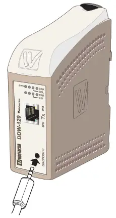
Information from the DIAG command
- Software release
- DIP switch settings
- If the unit is configured as CO or CPE
- If the unit is configured for Annex A or Annex B
- DSL link state
- DSL data rate (bit/s)
- DSL noise margin (dB)
- Ethernet data rate
- Ethernet duplex
Information from RUNDIAG command
- DSL link state
- DSL Data rate (bit/s)
- DSL Noise margin (dB)
The DDW-120 is ready for commando then the prompt “DDW” is transmitted to the supervisor system.
The commando RUNDIAG will continuously send the information. Approx update with 1s base. Commando is aborted by sending “any key to abort”.
Interface specifications
| Power | |
| Rated voltage | 12 to 48 VDC |
| Operating voltage | 10 to 60 VDC |
| Rated current | 330 mA @ 12 VDC 155 mA @ 24 VDC 80 mA @ 48 VDC |
| Rated frequency | DC |
| Inrush current, I2t | 0.23 A2s |
| Startup current* | 0.65 Apeak |
| Polarity | Reverse polarity protected |
| Redundant power input | Yes |
| Isolation to | All other |
| Connection | Detachable screw terminal |
| Connector size | 0.2 – 2.5 mm2 (AWG 24 – 12) |
| Shielded cable | Not required |
* If the external power supply is used it must meet the specified start-up current
| Service port | |
| Electrical specification | TTL-level |
| Data rate | 115.2 kbit/s |
| Data format | 8 data bits, none parity, 1 stop bit, no flow control |
| Circuit type | SELV |
| Transmission range | 15 m |
| Isolation to | All other |
| Galvanic connection to | None |
| Connection | 2.5 mm jack, use Westermo cable 1211-2027 |
| DSL | |
| Electrical specification | IEEE G.991.2 Annex B |
| Data rate | 192 kbit/s to 15304 kbit/s |
| Protocol | EFM according to IEEE 802.3-2004 |
| Transmission range | According to ITU-T G.991.2 depending on the line quality |
| Protection | Overcurrent/overvoltage protection circuit and varistor |
| Isolation to | All other |
| Connection | Detachable screw terminal |
| Connector size | 0.2 – 2.5 mm2 (AWG 24 – 12) |
| Shielded cable | Not required |
| Ethernet TX | |
| Electrical specification | IEEE std 802.3. 2000 Edition |
| Data rate | 10 Mbit/s, 100 Mbit/s, manual or auto |
| Duplex | Full or half, manual or auto |
| Circuit type | SELV |
| Transmission range | 100 m |
| Isolation to | All other |
| Connection | RJ-45 MDI or auto MDI/MDI-X |
| Shielded cable | Not required, except when installed in Railway applications as signaling and telecommunications apparatus and located close to rails* |
| Conductive housing | Isolated from all other circuits |
| Miscellaneous | If Auto-Neg. is disabled then this interface will be set MDI |
| Number of ports | 1 |
* To minimize the risk of interference, a shielded cable is recommended when the cable is located inside the 3 m boundary to the rails and connected to this port.
The cable shield should be properly connected (360°) to an earthing point within 1 m from this port. This earthing point should have a low impedance connection to the conductive enclosure of the apparatus cabinet, or similar, where the unit is built-in. This conductive enclosure should be connected to the earthing system of an installation and may be directly connected to the protective earth.
Connections
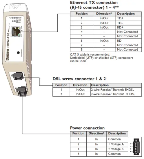
* Direction relative to this unit
** To minimize the risk of interference, a shielded cable is recommended when the cable is located inside the 3 m boundary to the rails and connected to this port. The cable shield should be properly connected (360°) to an earthing point within 1 m from this port. This earthing point should have a low impedance connection to the conductive enclosure of the apparatus cabinet, or similar, where the unit is built-in. This conductive enclosure should be connected to the earthing system of an installation and may be directly connected to the protective earth.
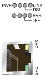
LED indicators
| LED | Status | Description |
| PWR (green) | OFF | No internal power |
| ON | Internal power ok / boot ok | |
| LFF (green) | OFF | LFF disabled |
| ON | LFF enabled | |
| ERR (red) | OFF | LFF not active |
| ON | LFF active, link fault on this unit | |
| Flash | LFF active, link fault on opposite unit | |
| DSL | OFF | No DSL link |
| ON | DSL link established | |
| Flash | DSL link negotiating | |
| LINK | OFF | No Ethernet link |
| ON | Ethernet link established | |
| Flash | Ethernet traffic indication | |
| SPD | OFF | Ethernet speed, 10 Mbit/s |
| ON | Ethernet speed, 100 Mbit/s | |
| OFF | Ethernet duplex, half | |
| ON | Ethernet duplex, full |
DIP-switch settings
![]() Before DIP-switch settings:
Before DIP-switch settings:
Prevent damage to internal electronics from electrostatic discharges (ESD) by discharging your body to a grounding point (e.g. use of a wrist strap). NOTE DIP-switch alterations are only effective after power on.
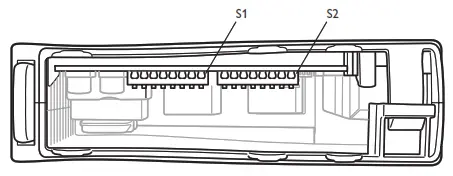
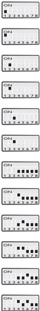
S1 DIP-switch
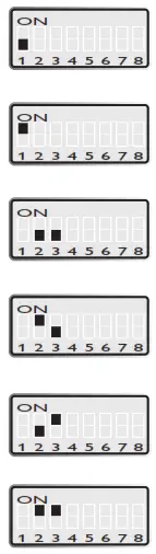 | Standard speed |
| Turbo speed | |
| Manual speed locked according to S2:4-8* | |
| Autobaud, normal mode** (Standard speed 192 kbit/s – 5.7 Mbit/s) (Turbo speed 192 kbit/s – 15.3 Mbit/s) | |
| Autobaud, high speed mode** (Standard speed 192 kbit/s – 5.7 Mbit/s) (Turbo speed 192 kbit/s – 15.3 Mbit/s) | |
| Autobaud, reliable mode** (Standard speed 192 kbit/s – 5.7 Mbit/s) (Turbo speed 192 kbit/s – 15.3 Mbit/s) |
 | CPE, Customer Premises Equipment |
| CO, Central Office | |
| LFF disabled | |
| LFF enabled |
S1: 6, 7, and 8 are not used
* Autobaud is recommended. When using manual locked speed user must make sure a correct noise margin is achieved. Westermo recommends at least a 3 dB noise margin for reliable operation.
** Negotiation of speed may take up to 3 minutes to complete.
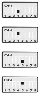
S2 DIP-switch
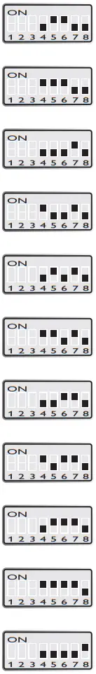 | Ethernet auto-negotiation disabled |
| Ethernet auto-negotiation enabled | |
| Ethernet speed 10 Mbit/s (if auto-neg. disabled) | |
| Ethernet speed 100 Mbit/s (if auto-neg. disabled) | |
| Ethernet half-duplex (if auto-neg. disabled) | |
| Ethernet full-duplex (if auto-neg. disabled) | |
| DSL-speed 192 kbit/s* DSL-speed 6200 kbit/s** | |
| DSL-speed 384 kbit/s* DSL-speed 6712 kbit/s** | |
| DSL-speed 512 kbit/s* DSL-speed 7224 kbit/s** | |
| DSL-speed 768 kbit/s* DSL-speed 7736 kbit/s** | |
| DSL-speed 1024 kbit/s* DSL-speed 8248 kbit/s** | |
| DSL-speed 1280 kbit/s* DSL-speed 8760 kbit/s** |
 | DSL-speed 2048kbit/s* DSL-speed 9272kbit/s** |
| DSL-speed 2304kbit/s* DSL-speed 9784kbit/s** | |
| DSL-speed 2688kbit/s* DSL-speed 10296kbit/s** | |
| DSL-speed, 3072 kbit/s* DSL-speed 10808kbit/s** | |
| DSL-speed, 3456 kbit/s* DSL-speed 11320kbit/s** | |
| DSL-speed, 3840 kbit/s* DSL-speed 11832kbit/s** | |
| DSL-speed, 4224 kbit/s* DSL-speed 12344kbit/s** | |
| DSL-speed, 4608 kbit/s* DSL-speed 13112kbit/s** | |
| DSL-speed, 4992 kbit/s* DSL-speed 13880kbit/s** | |
| DSL-speed, 5376 kbit/s* DSL-speed 14648kbit/s** | |
| DSL-speed 5696kbit/s* DSL-speed 15304kbit/s** |
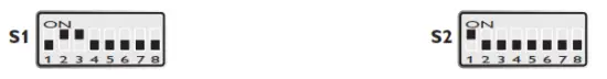
Factory settings
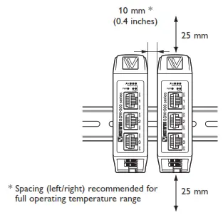
Mounting
This unit should be mounted on a 35 mm DIN-rail, which is horizontally mounted inside an apparatus cabinet, or similar. Snap-on mounting.
Cooling
This unit uses convection cooling. To avoid obstructing the airflow around the unit, use the following spacing rules. Minimum spacing is 25 mm (1.0 inches) above /below and 10 mm (0.4 inches) left /right of the unit. Spacing is recommended for the use of the unit in the full operating temperature range and service life.
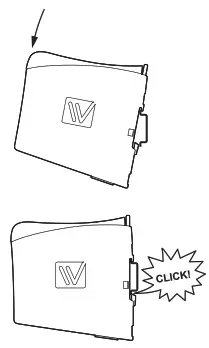
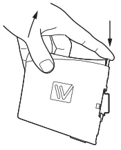
Removal
Press down the black support at the top of the unit.
![]()
Westermo • Metallverksgatan 6, SE-721 30 Västerås, Sweden
Tel +46 16 42 80 00 Fax +46 16 42 80 01
E-mail: [email protected]
www.westermo.com


