
PROSCEND 701EPI Long Reach Ethernet Extenders
Overview
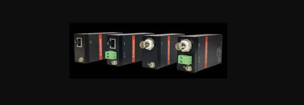
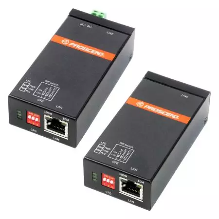
The 701EPI and 101EPI Long Reach Ethernet Extenders feature a pair of plug-n-play solution for carrying Ethernet traffic and power over Ethernet cables up to 800 meters. The 701CPI and 101CPI Ethernet-over-Coax Extenders deliver data and power over coaxial cables up to 1 km. The 701EPI and 701CPI are designed to locate at network sides where the 101EPI and 101CPI are located at the remote sides.
Specifications
| Model Name | 701EPI | 101EPI | 701CPI | 101CPI | |
|
LINE Interface | Connector | RJ45 x 1 | BNC 75 ohm x 1 | ||
| Compliance | IEEE 802.3/802.3u | ||||
| PoE | Passive PoE PSE | Passive PoE PD | Passive PoE PSE | Passive PoE PD | |
|
LAN Interface | Connector | RJ45 x 1 | |||
|
Compliance | IEEE 802.3/802.3u | IEEE 802.3/802.3u/ 802.3at/802.3af | IEEE 802.3/802.3u | IEEE 802.3/802.3u/ 802.3at/802.3af | |
| PoE | PSE | PSE | |||
|
Power Input | 2-pin Terminal Block 55 ~ 57 VDC | Powered by LINE interface | 2-pin Terminal Block 55 ~ 57 VDC | Powered by LINE interface | |
NOTE: Power Sourcing Equipment (PSE), Powered Device (PD)
LED Indicator
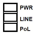
- LED Indicators of System
- There are three LEDs on the front panel of the 701EPI and 701CPI
LED Color On Off PWR Green Device Power On Device Power Off LINE Green Line LINK UP Line LINK DOWN PoL (Power over LINE) Green
Powered Device Connected Powered Device Disconnected - There are three LEDs on the front panel of the 101EPI and 101CPI.
LED Color On Off PWR Green Device Power On Device Power Off LINE Green Line LINK UP Line LINK DOWN PoE (Power over LAN) Green
Powered Device Connected Powered Device Disconnected
- There are three LEDs on the front panel of the 701EPI and 701CPI
- LED Indicators of Ethernet Port

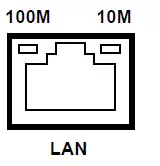
| LED | Blinking | On | Off |
| 10M | Data Transmitting | 10Mbps LINK UP | LINK DOWN |
| 100M | Data Transmitting | 100Mbps LINK UP | LINK DOWN |
RJ45 Pin Assignments
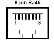
- Both 701EPI/101EPI LAN and LINE interfaces and the 701CPI/101CPI LAN interfaces are standard 8-pin RJ45 connectors. The following tables display the pinouts.
- The MDI/MDI-X pinouts of the 701EPI/101EPI LAN and LINE interfaces and the 701CPI/101CPI LAN interfaces.
| MDI Port Pinouts | MDI-X Port Pinouts | ||
| Pin | Description | Pin | Description |
| 1 | TX+ | 1 | RX+ |
| 2 | TX- | 2 | RX- |
| 3 | RX+ | 3 | TX+ |
| 4 | Not used | 4 | Not used |
| 5 | Not used | 5 | Not used |
| 6 | RX- | 6 | TX- |
| 7 | Not used | 7 | Not used |
| 8 | Not used | 8 | Not used |
- The PoE pinouts of the 701EPI/101EPI LINE interfaces.
PoE Pinouts Pin Description Pin Description 1 V+ 5 V+ 2 V+ 6 V- 3 V- 7 V- 4 V+ 8 V- - The PoE pinouts of the 101EPI/101CPI LAN interfaces.
PoE Pinouts Pin Description Pin Description 1 V+ 5 Not used 2 V+ 6 V- 3 V- 7 Not used 4 Not used 8 Not used
CFG (DIP Switch)
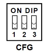
- The configuration descriptions of the 701EPI and 701CPI.
DIP Switch Mode ON OFF 1
PoL (Power over LINE) PoE Output Enabled
PoE Output Disabled
2
LFPT (Link Fault Pass Through)
LFPT Enabled
LFPT Disabled
3
Auto
100Mbps/10Mbps Auto Speed 10Mbps
- The configuration descriptions of the 101EPI and 101CPI.
DIP Switch Mode ON OFF 1
PoE (Power over LAN) PoE Output Enabled
PoE Output Disabled
2
LFPT (Link Fault Pass Through)
LFPT Enabled
LFPT Disabled
3
Auto
100Mbps/10Mbps Auto Speed 10Mbps
LFPT Behavior
Link Fault Pass Through (LFPT) is used for notifying the network administrator to get the long-distance cable status, as well as powering on and off the powered device located at the remote site. The following instructions explain the LFPT modes of DIP switches are in ON state for both the master 701EPI/701CPI and the remote 101EPI/101CPI devices.
- The 701EPI/701CPI detects LINK DOWN at its LINE interface when the cable is broken, it will pass this status to the network administrator by triggering LINK DOWN at its LAN interface.
- The 701EPI/701CPI detects LINK UP at its LINE interface when the cable is connected, it will pass this status to the network administrator by triggering LINK UP at its LAN interface.
- The 701EPI/701CPI detects LINK DOWN at its LAN interface when the cable is broken or the network administrator acts LINK DOWN, it will pass this status to the 101EPI/101CPI by triggering LINK DOWN at its LINE interface.
- The 101EPI/101CPI detects LINK DOWN at its LINE interface when the cable is broken or the 701EPI/701CPI acts LINK DOWN, it will turn off the PoE power output to the powered device connected to its LAN interface.
- The 701EPI/701CPI detects LINK UP at its LAN interface when the cable is connected or the network administrator acts LINK UP, it will pass this status to the 101EPI/101CPI by triggering LINK UP at its LINE interface.
- The 101EPI/101CPI detects LINK UP at its LINE interface when the cable is connected or the network administrator acts LINK UP, it will turn on the PoE power output to the powered device connected to its LAN interface.
Power Connection
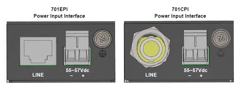
- The power input interfaces of the 701EPI and 701CPI are the 2-pin terminal block and are provided the power input voltage 55 ~ 57 VDC from the power supply.
- Insert the positive and negative wires into V+ and V- contact on the terminal block and tighten the wire-clamp screws to prevent the wires from being loosened.
Ground Connection
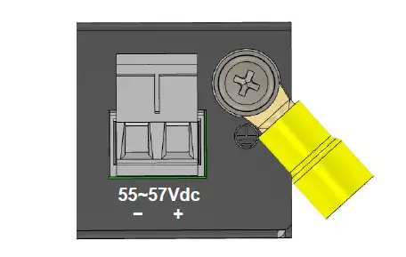
To prevent the effects of noise from electromagnetic interference (EMI), run the ground connection from the ground screw to the grounding surface before connecting the devices.
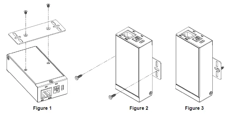
Wall Mounting
- STEP 1: At the rear side of the Ethernet Extender, use two screws to install the bracket, as shown in Figure 1.
NOTE: Each screw is flat head M3 x 4 mm. - STEP 2: Use the screws to attach the bracket of the Ethernet Extender for wall mounting, as shown in Figure 2 and Figure 3.
NOTE: These screws are not included in the package. The head of each screw is less than 7 mm in diameter, the shaft is less than 3 mm in diameter, and the length is less than 10 mm in diameter.
ATTENTION: Safety Warning
- Disconnect all power from devices before attempting installation.
- This device is intended for installation only in restricted access locations as defined where both these conditions apply:
- Access is through the use of a lock or tool and key, or other means of security, and is controlled by the authority responsible for the location.
- Access can only be gained by service persons or by users who have been instructed about the reasons for the restrictions applied to the location and about any precautions that shall be taken.
- All-electric installations must be carried out in accordance with local and national regulations.
- Do not work on the system, connect or disconnect cables during periods of lightning activity.
- The equipment must be connected to earth.
- The shield of RJ45 cables has to be connected to the same earth potential as the equipment.
- Please remove the ground connection lastly if you need to remove the device after installation.
- If the LINE interface is used for the connection between two buildings, all necessary protective measures must be ensured externally.
- This equipment relies on the building’s installation for short-circuit (overcurrent) protection. Ensure that a fuse or circuit breaker no larger than 1A is used.
NOTE:
- Please scan below QR Code to download online resources.
- 701EPI/101EPI download link: https://www.proscend.com/en/product/701-101E.html
- 701CPI/101CPI download link: https://www.proscend.com/en/product/701-101C.html