![]() LINE-EXTENDER
LINE-EXTENDER
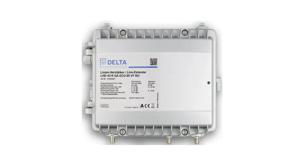
LHD 43 (R) GA ECO, LHD 43-1 (R) GA ECO
User manual
![]()
LHD 43,43-1 Line Extender
Line-extender
Downstream gain: 42,5 dB
Upstream gain: 28 dB
Features:
Cablesimulator DS
Attenuator DS 0…20dB
Equalizer DS 0…25 dB
Interstage slope DS 0…20 dB
Return path amplifier integrated
Fostra-F US attenuator 0/6/45 dB
Equalizer US 0…16 dB
Attenuator US 0…30dB
Die-cast housing
Safety Instructions
Read and observe these safety instructions carefully before installing or commissioning the unit!
To avoid danger to life and limb, the units may only be installed, connected, and commissioned by appropriately trained personnel. This applies to locally supplied units with 230V mains voltage as well as to remotely supplied units with a supply voltage of up to 65VAC. If a unit is damaged, it must be disconnected from the power supply immediately.
To avoid dangerous overvoltages (can e.g. lead to fire hazards and danger to life), care must be taken to ensure proper connection and correct earthing of the connected devices or the entire system installation. In particular, the standards EN 60728-11 and EN 62368-1 must be taken into account and observed with regard to safety. With regard to electromagnetic compatibility (avoidance of excessive emitted interference or too low interference immunity), the standard EN 50083-2 must be observed. It is also important that only high-quality connection cables are used for the signal lines, which have at least a shielding class A (according to EN 50083-2).
The installation site must allow safe routing of all connected cables. Power supply cables and feed cables must not be damaged or crushed by other objects. It is also essential to ensure that no cables come into the direct vicinity of heat sources (e.g. radiators, other electrical appliances, fireplaces, etc.).
Plan the installation site so that you can easily reach the mains plug and pull it out of the socket in case of danger. Select the installation site in such a way that unauthorized persons, especially children, and pets, cannot gain access to the units in order to avoid possible damage to life and limb.
The installation site must be adequately protected against moisture and splash water. It should also not be located in the immediate vicinity of water-bearing pipes or installations so that water cannot get into the units if they are damaged, which could lead to short circuits and fires. This applies in particular to units with open-air vents and to all units that are not protected by an appropriate protection class.
To prevent hazards from falling metal parts and possible short circuits (which could lead to fires), it is mandatory to mount units with ventilation slots according to the preferred direction shown. This always applies as long as the installation is carried out at a height of fewer than 2 meters.
Ventilation slots and heat sinks are important functional elements on the units. For units with heat sinks or ventilation slots, it is therefore essential to ensure that they are not covered or obstructed under any circumstances. Also, ensure that there is ample air circulation around the unit. This will prevent possible damage to the unit and the risk of fire due to overheating.
To avoid both damage to the unit and possible consequential damage, units intended for wall mounting must only be mounted on a flat surface.
For units with a local supply of 230 VAC mains voltage: Before opening the unit, pull out the mains plug or remove the power supply, otherwise, there is a danger to life. This also applies when cleaning the unit or working on the connections. Repairs to the unit may only be carried out by a specialist in compliance with the applicable standards.
If there is a replaceable fuse, pull out the main plug before changing the fuse. Defective fuses may only be replaced by standard-compliant fuses of the same nominal value. If the device is equipped with a protective contact plug or a device socket with a PE connection, the device must be commissioned using a suitable protective contact socket.
For remotely powered units with a maximum supply voltage of 65 VAC: The unit may only be accessed by trained and skilled personnel and may only be opened by them in order to switch the supply voltage on or off via the respective plug-in fuses. The qualified personnel must follow the warnings regarding dangerous voltages. Mounting and fixing the unit: When mounting the device, make sure that the mounting location has sufficient stability with regard to the weight of the device. Screws and dowels required for mounting should be sufficiently dimensioned to hold twice the weight of the unit. Masonry or concrete is recommended as the mounting surface, screws should have a diameter of 4-5mm.
Connection of the protective conductor according to EN 60728-11 clause 6: Protective equipotential bonding system must be carried out via the earthing connection point on the housing (marked![]() with ). A protective conductor with a cross-section of min. 2.5mm² copper (mechanically protected) or 4.0mm² copper (mechanically unprotected) must be used. The cable shield of a subscriber cable must either be connected to the device earth or galvanically separated. The cable shield of a connected antenna that does not have to be earthed must be connected to the unit earth. All earth connections must be made in such a way that the connection can only be disconnected with the aid of tools. The usual connection of a cable shield to the metal body of the socket is sufficient for this purpose.
with ). A protective conductor with a cross-section of min. 2.5mm² copper (mechanically protected) or 4.0mm² copper (mechanically unprotected) must be used. The cable shield of a subscriber cable must either be connected to the device earth or galvanically separated. The cable shield of a connected antenna that does not have to be earthed must be connected to the unit earth. All earth connections must be made in such a way that the connection can only be disconnected with the aid of tools. The usual connection of a cable shield to the metal body of the socket is sufficient for this purpose.![]() Caution, hot surfaces: The housing surface can become very hot, especially at higher ambient temperatures (from approx. 45°C), so it should not be touched directly during operation.
Caution, hot surfaces: The housing surface can become very hot, especially at higher ambient temperatures (from approx. 45°C), so it should not be touched directly during operation.
Transmission parameter
| Transmission parameter | |||||
| Downstream | |||||
| units | min. | typ. | max. | remarks | |
| Frequency range | MHz | 85 105,258*) | 1218 | Modular diplexer | |
| Gain | dB | 42 | 42,5 | 43 | Port to port gain Incl. diplexer |
| Ripple | dB | ±0,5 | ±0,75 | ||
| Input attenuator | dB | 0 | 20 | 1 dB steps Factory preset -20dB | |
| Input equalizer | dB | 0 | 25 | 1 dB steps | |
| Interstage attenuation | dB | 0 | 6 | UPP1 | |
| I Slope | dB | 0 | 20 | 1 dB steps | |
| Return loss input and output | dB | ≥20 – 1,75 / Okt. ≥20 – 2 / Okt. ≥20 – 3 / Okt. min 12 @ 1218MHz | 65-1218MHz 85-1218MHz 204-1218MHz | ||
| Noise figure | dB | 7 | 8 | ||
| Output level 41 Ch, CENELEC, flat, CSO/CTB>60 dB | dBµV | 111 | EN60728-3 Ohne / without K2 | ||
| Max. operating level, flat Umax (N) (BER ≤ 10-9) | dBµV | 104,5 | EN60728-3 N=119 | ||
| Max. Betriebspegel, slope 9dB Max. operating level, slope 9dB Umax (N) (BER ≤ 10-9) | dBµV | 106 | EN60728-3 N=119 | ||
| Upstream | |||||
| units | min. | Typ. | max. | remarks | |
| Frequency range | MHz | 5 | 65 85 204*) | Onboard Select by diplexer | |
| Verstärkung / Gain | dB | 27,5 | 28 | 28,5 | |
| Noise figure | dB | 6 | 8 | ||
| Interstage slope | dB | 0 | 16 | 1 dB steps | |
| Output attenuator | dB | 0 | 30 | 1 dB steps Factory preset -20dB | |
| Rückflussdämpfung Ein- & Ausgang / Return loss input and output | dB | ≥15 ≥20 | 5-10MHz 10-65/85/204Hz *) | ||
| Eingangspegeldichte/Input level density 50dB NPR @ 180MHz load Dynamic range 24dB | dBµV/Hz | -6 | 18 | ||
| Max. level flat Umax (N) (BER ≤ 10-9) | dBµV | 107 | EN 60728-3 N=24 | ||
Depends on the diplexer configuration
Electrical and general RF specification
| units | min. | typ. | max. | remarks | |
| Input power rated voltage | V ~ V ~ | 200 28 | 240 65 | 50 Hz 50 Hz | |
| Power supply type | Switch mode power supply | ||||
| Power cord length | m | 1,1 | 1,3 | ||
| Power cord type | Euro | ||||
| Power consumption | W | 12,7 12,7 | bei / at 230 V~ bei / at 50 V~ | ||
| Max. remote current | A ~ eff | 10 | |||
| Consumption related to remote voltage | A ~ eff | 0,68 | 28 VAC | ||
| A ~ eff | 0,63 | 30 VAC | |||
| A ~ eff | 0,55 | 35 VAC | |||
| A ~ eff | 0,49 | 40 VAC | |||
| A ~ eff | 0,44 | 45 VAC | |||
| A ~ eff | 0,41 | 50 VAC | |||
| A ~ eff | 0,37 | 55 VAC | |||
| A ~ eff | 0,34 | 60 VAC | |||
| A ~ eff | 0,32 | 65 VAC | |||
| HUM modulation | dB | > 60dB | @ 7A | ||
| Ambient temperature | °C | – 30 | + 60 | ||
| Input / output impedance | Ohm | 75 | |||
| Safety requirements | nach / acc. EN 60728-11 EN 62368-1 | ||||
| EMC – conditions Radiated power Screening efficiency | dBpW | nach / acc. to EN 50083-2 | |||
| Protective system | IP 65 | ||||
| Overvoltage protection | kV | 6 | EN 60728-3 | ||
| Protection class | II | Ortsgespeiste Version 230V/ with local supply 230V | |||
| Conformity |  | ||||
| article number | LHD 43 GA ECO 85 VF RO | 57004292 |
| LHD 43 R GA ECO 85 VF RO | 57002811 | |
| LHD 43-1 R GA ECO 85 S | 57004319 |
Mechanical data
| units | min. | typ. | max. | remarks | |
| Dimension W x H x D | mm | 225 x 195 x 95 | Die cast housing | ||
| Weight | kg | 1,8 | |||
| No. of inputs | pcs. | 1 | |||
| No. of outputs | pcs. | 1 | 2 (3*) | * -1 Typ | |
| No.of test points | pcs. | 2 | |||
Accessories, optional
| Type | Description | No. |
| FOSTER-F | FOSTER F V2.1 Tuneable VER | 57003909 |
| AGC 503 G | Auto-Gain-Control, 2Tone AGC (ALSC) | 57003964 |
| AGC 502 G | Auto-Gain-Control for LHD/NVD | 57004163 |
| RLK 565-1 | Diplexer 5-65 / 85-1218MHz | 57002732 |
| RLK 585-1 | Diplexer 5-85 / 105-1218MHz | 57002733 |
| RLK 5200 | Diplexer 5-204 / 258-1218MHz | 57002776 |
| LPF 5-65 | Low Pass Filter 5-65 MHz | 57002295 |
| LPF 5-85 | Low Pass Filter 5-85 MHz | 57002296 |
| LPF 5-204 | Low Pass Filter 5-204 MHz | 57002820 |
| HPF 85-1 | High Pass Filter 85-1218 MHz | 57002297 |
| HPF 105-1 | High Pass Filter 105-1218 MHz | 57002298 |
| HPF 258-1 | High Pass Filter 258-1218 MHz | 57002819 |
| PAD xL | Attenuation PAD 0 dB…20 dB | 10161523…43 |
PG11 adapter or 5/8“ hardline connectors must be ordered separately
Mounting instructions for hardline connectors – length of the inner conductor
Shorten inner conductor to length L
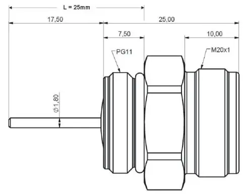
Kabelarmatur-Muttern mit
5/8“-Kabelarmatur: L = 27,0mm
PG11-Kabelarmatur: L = 25,0mm
Use only hardline connectors with an O-ring seal.
The hardline connector nut was tightened with an open wrench.
5/8“-hardline connector: L = 27,0mm
PG11-hardline connector: L = 25,0mm
Block diagram
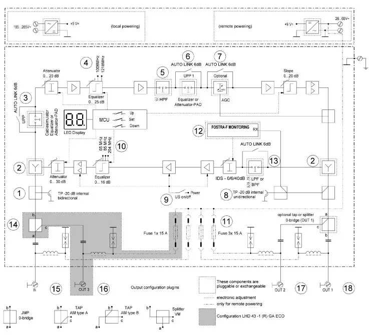
Inner View
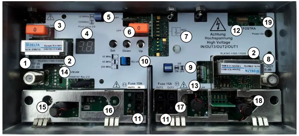
| 1. TP IN -20dB 2. Diplexer RLK565-1/585-1/5200 3. Cablesimulator DS 4. Pivot point DS 1006/1218MHz 5. DS/ HPF85-1/105-1/258-1MHz 6. UPP1/ Universal plug-in station 7. AGC module 8. TP OUT -20dB 9. US/ON/OFF Jumper 10. EQ US 65/85/204MHz | 11. Fuse OUT3/IN/OUT2/OUT1 12. FOSTER 13. US/ LPF5-65/5-85/5-204MHz 14. VM/AM Splitter or Tap / LHD 43-1 GA ECO, LHD 43-1 R GA ECO 15. RF IN 16. RF OUT3 / LHD 43-1 GA ECO, LHD 43-1 R GA ECO 17. RF OUT2 18. RF OUT1 19. Power ON LED |
Operating functions

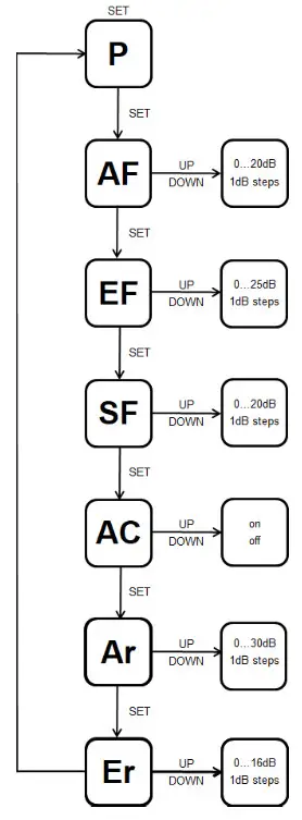
P Programming mode
AF A attenuator Forward
EF Equalizer Forward
SF interstage Attenuator
AC A automatic return path Control
Ar A attenuator reverse
Er Equalizer reverse
Auslieferungszustand AF + Ar = -20dB
Factory preset AF + Ar = -20dB
AC-setup:
OFF→ Factory setup) Manual setup of upstream equalizer and attenuator
ON → Automatic setup of upstream equalizer in dependence on the downstream setup., The setup of the upstream is related to a fixed downstream level of the previous Remote PHY device of 110 dBµV
| DoA Return back the equipment [Defect on Arrival) l Delta – form sheet C 118 | Please fill out and attach register your return tom’ sheet to the defective device before shipping and/or transfer the data into our RMA form. before shipping: [email protected] | |
| Number of our original delivery note | Complained device type (model) | |
| Number of the material pre-replacement delivery note | Our OR-Code or your unique reference number
| |
| Service Partner (e.g. company stamp) | Fault description. error message [ ] Power supply without voltage [ ] Power supply working, but [ ] signal level fluctuation, [ ] no output signal Other malfunction: | |
| possibly internal ID-number | Date | the malfunction did you notce7 ‘Detective is no suffix ent information to be ,: sed as feedback) |
Advice and hint: In case of the too-low output signal at optical nodes, please clean the surfaces of the fiber optic connectors & junctions and test again before sending back the equipment_ For too-low RF signal, please check the different attenuator settings. as well.
DCT DELTA AG, Bodanrueckstrasse 1, 78351 Bodman, Deutschland,
www.dct-delta.de,
[email protected]
Montageanleitung MA 29001505 LHD 43 xxxx ECO, Stand 13.12.2021


