Rising Digital SECD7I0B03H Sany Encourage Integrated Display

Preface
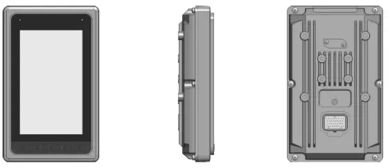
- SECD-7I0B-03 (H) is a monitoring and control platform specially designed for construction machinery and adopts a 7.0-inch, 800×480 resolution TFT industrial-grade liquid crystal display, which has good human-computer interaction performance.
- In addition to the display function, it also integrates control and communication functions: support digital and analog signal input
and output, motor control, CAN, LTE, GPS, and can seamlessly connect with the remote monitoring center. - The display adopts a flat-panel front panel design with a beautiful industrial appearance. Electromagnetic compatibility, IP protection, and high level of anti-vibration impact can meet the environmental index requirements of harsh working conditions.
- It supports the LM Studio integrated development environment independently developed by Huaxing, and the configuration program and screen development are easy.
Functions and features
Integration of control, display and communication
- Display: Exquisite and practical industrial-grade TFT LCD screen, which can realize thedisplay of various components
- Control: 5 channels of switch input, 6 channels of switch/PWM output, 8 channels of analoginput, 1 channel of motor drive output
- Communication: support a variety of wired and wireless communication technologies,compatible with J1939/CANOpen/CAN2.0B protocol; support USB program and quick downloadof pictures
- The function overview is as follows:
Numbering Features Sub-number Subfunction description 1
display
1.1 Picture switch Press the button to turn the page 1.2
Variable display
Display variable value at specified position
1.3
Icon display
Display a customized icon in the specified location
1.4
Bar graph display
The progress bar shows the associated variable value
1.5
Cut picture
Cut the picture to a custom target location
2
communication
2.1
CAN communication
Receive the CAN data of the Huaxing controller and send it to the configuration software after processing; receive the data of the configuration software and send it to the controller;
2.2
LTE communication, GPS communication
Upload data to the remote monitoring center; receive data from the monitoring center; receive satellite latitude and longitude information
2.4
GPRS remote debugging and update of LM configuration
The remote technical support center can perform remote LM debugging and brushing
2.5
USB update program and pictures
After plugging in the USB with HMI configuration, the configuration and picture will be updated automatically after power on
3 control 3.1 Process control Realize the sequence relationship, branch relationship, and cycle relationship in the task body software
3.2
Parameter feature modification
Component parameter format definition 3.3
Integer operations
Integer definition, assignment, extreme value, limiting, four arithmetic operations, logic operations, comparison and other functions
3.4
Floating point arithmetic
Realize floating-point number definition, assignment, extreme value, limiting, four arithmetic operations, elementary function operations, comparison and other functions
3.5
Data conversion processing
Realize normalization processing, data conversion processing between different types of data and different engineering quantities
3.6
Selection function
Realize the choice relationship between number and number
3.7
Approximation function
Provides approximate calculation methods such as the Taiwanese series approximation of the piecewise continuous function and the multi-segment straight line
approximation of the curve
3.8
Time function
Realize a class of functions that are used in discrete manufacturing and batch process industries, which are related to time and use switching and analog as output functions
3.9
Process volume processing
Provides a class of functional functions for process industry automation (including specific calculation methods for engineering quantities such as flow and temperature)
3.10
Control typical links
Provides typical links for controller design and control system simulation
3.11
PID controller
Provides a PID controller that accounts for more than 90% of the total control
loop 3.12
Dedicated TSO controller
Provides the unique “transient-steady-state-overshoot” controller and two-position controller unique to LM measurement and control components
3.13
filter
Provides Butterworth filters for process industry automation
4
Human-computer interaction
4.1 Keyboard scan Support 5 buttons 4.2
Power saving function
Screen brightness automatic/manual adjustment
5
input Output
5.1 Switch input Support switch input 5.2 Analog input Support analog input 5.3 Frequency input Support TI input 5.4 Switch output Support switch output 5.5 Analog output Support analog output 5.6 Motor output Support stepper motor output
- Dedicated display and control development environment Huaxing’s self-developed LM Studio display and control development environment, based on the IEC61149 standard, provides LM Studio-GUI screen preparation tools, and integrates a large number of function blocks to quickly develop screens and configuration programs.
- Adapt to harsh environments Can be used in severe cold and hot environments: -25 degrees low temperature, 65 degrees high temperature Anti-reverse power supply design, self-protection greater than 37V to prevent burnout Suitable for environments such as strong vibration, dusty rain and lightning strikes in field operations
- It can be seamlessly connected with Huaxing remote monitoring system Support remote debugging and brush program, convenient for after-sales maintenance Support remote unlocking machine to facilitate credit management
external interface function description
External interface definition
Installation size
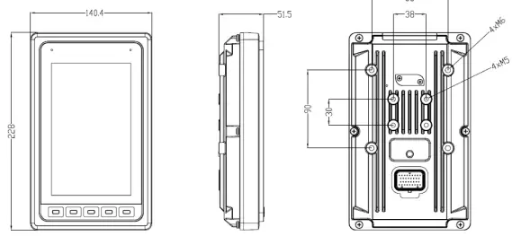
Can be fixed and installed with 4×M6 screws (including spring washers and flat washers)
Definition of connector port
| classification | Port type | The port number | Corresponding to M4-MCU pin | Mode selection/feedback | Features |
| Voltage type analog input | AI_V_1 | J1-21 | PA1_ADC12_IN1 | High-speed AD sampling: Input: 0~10V.DC, Accuracy: 0.5%, Resolution: 0.025% | |
| AI_V_2 | J1-29 | PA1_ADC12_IN2 | |||
| AI_V_3 | J1-30 | PA1_ADC12_IN3 | |||
| AI_V_4 | J1-32 | PA1_ADC12_IN4 | |||
| AI_V_5 | J1-4 | PA1_ADC12_IN5 | |||
| AI_V_6 | J1-5 | PA1_ADC12_IN6 | |||
| Resistive analog input | AI_R_1 | J1-23 | PA1_ADC12_IN7 | The sampling range is set by the duty cycle, the sampling accuracy is 0.5%, and the resolution is 0.025%; 0~30KΩ | |
| AI_R_2 | J1-31 | PA1_ADC12_IN8 | |||
| Switch input (low effective) | DI_L_1 | J1-12 | PH4 | PA9(DO) The default is DI_L, when PA9 is high, it is DI_H | High and low level switching is detected, Low level (0-4.55V) High level (4.55-36V) Frequency: 0~1KHz |
| DI_L_2 | J1-13 | PH3 | |||
| DI_L_3 | J1-14 | PH8 | |||
| DI_L_4 | J1-15 | PF8 | |||
| DI_L_5 | J1-6 | PE3 | |||
| Frequency input | TI_1 | J1-3 | PA8 | PF7(DO) The default is TI_1 pull high, when PF7 is high, pull low | 12-24V.DC Frequency:10Hz~70KHz, Accuracy: 0.1% |
| PWM/switch output | PWM_1/DO_1 | J1-10 | PB7 | PB1_ADC12_IN9 | Pulse width modulation output: Frequency: 50~2.55kHz, Current 0~1.5A, 1% accuracy, 0.025% resolution |
| PWM_2/DO_2 | J1-18 | PB8 | PC1_ADC123_IN11 | ||
| PWM_3/DO_3 | J1-26 | PB9 | PC2_ADC123_IN12 | ||
| PWM_4/DO_4 | J1-27 | PB10 | PC3_ADC123_IN13 | ||
| PWM_5/DO_5 | J1-28 | PB11 | PC4_ADC12_IN14 | ||
| PWM_6/DO_6 | J1-22 | PF6 | No feedback on this route | ||
| Motor drive output | MO_A+ | J1-11 | Stepper motor control Contact capacity: 40V.DC 1.2A, Frequency: 0~130Hz, Features: overvoltage, short circuit protection | ||
| MO_A- | J1-16 | ||||
| MO_B+ | J1-19 | ||||
| MO_B- | J1-20 | ||||
| Reset | Reset | J1-7 | Short circuit with ground for more than 5 seconds to reset | ||
| Key switch | SMI Key switch | J1-17 | Judge whether the key switch is turned on when input 24V or not | ||
| Ground | GND | J1-8,24,33 | Ground | ||
| Power supply | +5VOUT | J1-9 | Power supply for external devices,
Maximum output 750mA |
| Power positive | Power positive | J1-25,34 | Power supply 12-24V | ||
| CAN bus | CANA_H | J1-2 | |||
| CANA_L | J1-1 |
| Internal control pin | ||
| Features | Corresponding to M4-MCU pin | Remarks |
|
Key scan | PG10 (DI), line scan | Key code 1-key S5 Key code 3-key S1 Key code 4–button S2 Key code 5–button S3 Key code 6-key S4 |
| PG13 (DI), line scan | ||
| PG14 (DI), line scan | ||
| PG2 (DI), column scan | ||
| PG3 (DI), column scan | ||
| Two hours to trigger the reset port | PI3 | Output |
| 24VDRV start | PI11 | Output |
| SMI signal detection | PI8 | input |
| buzzer | PB12 | Output |
| AUO screen backlight control | PE5 | Output |
| AUO screen brightness adjustment | PC8 | Output |
| ARM 24 signal detection | PA0_ADC123_IN0 | input |
Development and debugging
Hardware development platform
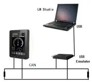
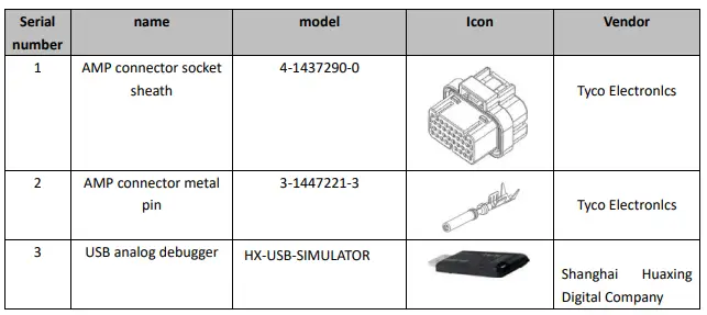
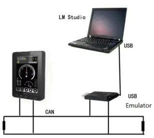
Connect the PC to the LM USB emulator via USB, and connect the other end of the emulator to the SECD-7I0B-03 (H) display screen via CAN. Install Huaxing’s dedicated integrated development environment LM Studio on the PC. Complete the construction of the hardware platform. When purchasing products, relevant development and debugging accessories must be equipped at the same time, as shown in the following table:
Software development platform
LM Studio supports application development based on Huaxing’s special LM language, and provides a software platform integrating project management, code writing, compilation, and debugging functions for Huaxing’s controller and display product application development, and improves application development efficiency and quality. With the help of the GUI programming module of LM Studio, users can develop in a graphical manner. They only need to create some controls on the interface and associate these controls with the corresponding variables. At the same time, some LM script programs corresponding to the keys are added to realize what you see is what you get.
LM Studio integrates a large number of mature and easy-to-use component libraries, as follows:
| Component number | Big category | Category description | Function introduction |
| 1.1 | System kernel | System functions | Implement system definition |
| 1.2 | Mission control | Realize the definition of task body | |
| 2.1 |
Basic services | Process control | Realize the sequence relationship, branch relationship, and cycle relationship in the task body software |
| 2.2 | Parameter feature modification | Component parameter format definition | |
|
2.3 | Integer operations | Integer definition, assignment, extreme value, limiting, four arithmetic operations, logic operations, comparison and other functions | |
|
2.4 | Floating point arithmetic | Realize floating-point number definition, assignment, extreme value, limiting, four arithmetic operations, elementary function operations, comparison and other functions | |
|
2.5 |
Data conversion processing | Realize normalization processing, data conversion processing between different types of data and different engineering quantities | |
| 2.6 | Selection function | Realize the choice relationship between number and number | |
|
2.7 |
Approximation function | Provides approximate calculation methods such as the Taiwanese series approximation of the piecewise continuous function and the multi-segment straight line approximation of the curve | |
| 3.1 |
communication | CAN communication | Realize CAN data transmission |
| 3.2 | GPRS/GPS communication | Realize GPRS/GPS data transmission | |
| 3.3 | Serial communication | Realize RS232 serial data transmission | |
| 4 | input Output | Input and output drive | Realize digital input and output, analog input and output, pulse input, motor output, and real-time clock, keyboard, encoder and other peripheral communication |
|
5.1 |
Time function | Realize a class of functions that are used in discrete manufacturing and batch process industries, which are related to time and use switching and analog as output functions | ||
|
Process volume | Provides a class of functional functions for process industry automation (including specific calculation methods for engineering quantities such as flow and temperature) | |||
| 5.2 |
typical application | processing | ||
| 5.3 | Control typical links | Provides typical links for controller design and control system simulation | ||
| 5.4 | PID controller | Provides a PID controller that accounts for more than 90% of the total control loop | ||
|
5.5 |
Dedicated TSO controller | Provides the unique “transient-steady-state-overshoot” controller and two-position controller unique to LM measurement and control components | ||
| 5.6 | filter | Provides Butterworth filters for process industry automation | ||
| 6.1 |
GUI screen | GUI system | Build GUI system | |
| 6.2 | GUI graphic control library | Create page, icon, text, bar graph, meter pointer and other controls | ||
| 6.3 | GUI script library | Dedicated to the process control, numerical calculation and timer function of the GUI system | ||
For specific component applications, see “LM Reference Manual” under the “Help” menu of the LM Studio software.
Application examples
Screen compilation
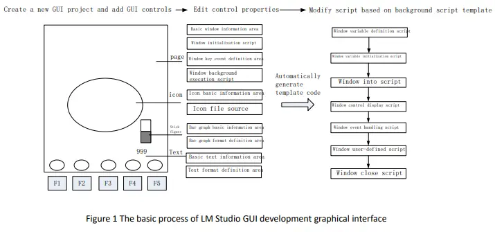
The screen preparation adopts the graphical “what you see what you get” method for development. It includes the following steps:
- Create a new GUI project
- Add GUI controls
- Generate GUI code template

Create a new GUI project
For details, see “Help Content” under the “Help” menu of the LM Studio software.
Add GUI controls
Page control definition
Generate background GUI script code
Double-click the page to automatically generate the background script code corresponding to the page.
Control and communication programming
IO input and output function
- 1-4.3 horizontal screen;
- 2—5.0 vertical screen
- 3—7.0 Portrait
- After the first line is over, press Enter, and write GUILib: V. in the second line. After the second line is over, press Enter to save and exit.
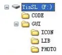
Create three folders, ICON, LIB, and PHOTO under the GUI folder
- LIB folder—used to place font files, the naming of font files conforms to XXXX.DZK (X is Arabic numerals)
- PHOTO folder—used to store picture files, the pictures are converted from the host computer download tool, and the name conforms to XXXX.bmp (X is Arabic numerals)
- ICON folder—used to place icon files

Burning steps
- Before burning the picture font library, make sure that the bottom layer has been burned. You can open the configuration debugging interface to connect to the code file to observe whether it can communicate. If it fails to communicate, first reset the motherboard and try again.
- After adding the files to be burned in the U disk according to the second step, connect it to the USB port of the motherboard, and then power on the motherboard.
- Under normal circumstances, the display screen will start to flash and display burned pictures after a few seconds, and the U disk indicator light will start to flash.
- If you cannot see the burning process, please make sure to unplug the U disk under the premise that the U disk indicator is not flashing.
Description of environmental indicators
- Working temperature: -20~+65 ℃ Storage temperature: -25~+80 ℃
- Overvoltage protection: 37V
- Vibration resistance: 8.3-400Hz 10mm 6.8g Shock resistance: 50g, 6ms&11ms Relative humidity: 10%~90%
- Protection level: IP65
Connect with external controller
Connect with external controller device via CAN bus, support CAN2.0B, Canopen, J1939 protocol.
Common troubleshooting
- The connection between the display case and the grounded metal part should have a low impedance value. It is qualified by the following test. When the transient interference is injected, the voltage drop is measured between the controller case and the grounded metal parts. It is required that the voltage Umax on the case should not be greater than 0.8V (TTL low level threshold) during the entire process of interference injection; According to some characteristic parameters during the interference injection, the required ground impedance range is calculated: in the 0-100MHz frequency band, the impedance value shall not exceed 60 milliohms;
- In addition to the good grounding of the display shell, all input and output points of sensors, loads, etc. connected to the display must be connected in a closed loop, that is, all input and output grounds must be connected to the corresponding ground of the display.
- The common reasons for unsuccessful burning of picture fonts are as follows:
- The configuration file does not exist or the content is wrong
- Wrong naming of the folder to be burned, no burned file or wrong file naming format
- Problems with the USB flash drive or motherboard
- The underlying program is not burned or the version is wrong
FCC Statement
Any Changes or modifications not expressly approved by the party responsible for compliance could void the user’s authority to operate the equipment.
This device complies with part 15 of the FCC Rules. Operation is subject to the following two conditions:
- This device may not cause harmful interference, and
- This device must accept any interference received, including interference that may cause undesired operation.
FCC Radiation Exposure Statement:
This equipment complies with FCC radiation exposure limits set forth for an uncontrolled environment. This equipment should be installed and operated with minimum distance 20cm between the radiator& your body.
Note: This equipment has been tested and found to comply with the limits for a Class B digital device, pursuant to part 15 of the FCC
Rules. These limits are designed to provide reasonable protection against harmful interference in a residential installation. This equipment generates uses and can radiate radio frequency energy and, if not installed and used in accordance with the instructions, may cause harmful interference to radio communications. However,there is no guarantee that interference will not occur in a particular installation. If this equipment does cause harmful interference to radio or television reception, which can be determined by turning the equipment off and on, the user is encouraged to try to correct the interference by one or more of the following measures:
- Reorient or relocate the receiving antenna.
- Increase the separation between the equipment and receiver.
- Connect the equipment into an outlet on a circuit different from that to which the receiver is connected.
- Consult the dealer or an experienced radio/TV technician for help.


