RISING SEED7I0A55 5.5 Generation Intelligent Screen

Functions and features
- 7 Inch Touch screen with capacitive touch
- Internal integrated radio with external radio antenna
- Microphone voice input, audio output
- 4G, GPS, BLE
- Support two-way can communication, support ISO11898 CAN2.0B、J1939、CanOpen
- The interface uses te 2-6447232-3 connector. It is recommended that the harness connector te 4- 1437290-0, and the model of the matching terminal is 3-1447221-3
- Function overview
| Item | function | Subnumber | Subfunction | describe |
| 1 | Display | 1.1 | Page switching | Page switching is realized by touching the key |
| 1.2 | Variable display | Displays the variable value at the specified location | ||
| 1.3 | Icon display | Displays a custom icon at the specified location | ||
| 1.4 | Bar chart display | The progress bar displays the associated variable values | ||
| 1.5 | Cut pictures | Cut image to custom target location | ||
| 1.6 | Picture in picture display | Picture in picture display of custom target position | ||
| 2 | communi- cation | 2.1 | CAN communication | support ISO11898 CAN2.0B、J1939、CanOpen |
| 2.2 | 4G communication | Upload the data to the remote monitoring center; receive the data from the monitoring center, and support 4G LTE high-speed transmission (Please insert SIM card before using) | ||
| 2.3 | GPS communication | Receive satellite’s longitude and latitude information | ||
| 2.4 | USB communication | Support u disk upgrade program and U listen to songs and other functions | ||
| 2.5 | BLE communication | Support BLE and smart phone connection, Upload the data and other functions(Match your phone before using it) | ||
| 3 | human- computer interaction | 3.1 | Touch the button | Support capacitance touch function |
| 3.2 | Light sensing | Support light sensing function | ||
| 3.3 | FM | Internal integrated radio function | ||
| 3.4 | Music playing | Support Bluetooth and USB flash disk | ||
| 4 | 4.1 | Switch input | Support switch input |
| Inpu/ output | 4.2 | Output switch | Support switch output | |
| 4.3 | Audio analog signal output | Audio analog signal output | ||
| 5 | camera | 5.1 | Camera acquisition and display function | Support NTSC / PAL analog camera, can access 1 channel, support single picture, picture in picture display |
| 6 | Microphone | 6.1 | Microphone input | Support microphone input, Bluetooth phone function |
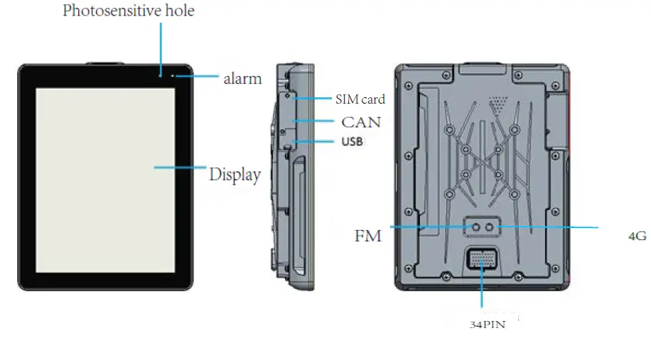
Product appearance structure-function description
Appearance size
unit: mm
Installation dimensions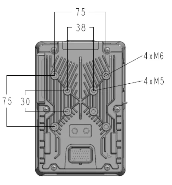
The outer ring is fixed with 4 × M6 screws (including spring washer and flat washer), and the inner ring is fixed with 4 × M5 screws (including spring washer and flat washer).
Product port function details
| name | function | Pin | remarks | |
| digital signal input | System settings | SYS_SET | 3 | Power on and ground short circuit into BIOS, wiring harness is not connected |
| signal | DI | 30 | One key start signal | |
| Digital signal output | signal output | DO | 8 | Electrical signal on battery |
| signal output | DO | 9 | Start signal | |
|
Audio output | Audio ground | A_GND | 5 | Power amplifier |
| Audio power supply | A_POWER | 4 | Power supply of power amplifier | |
| Left vocal tract | A_LF | 6 | Left channel | |
| Right vocal tract | A_RF | 7 | Right channel | |
| MUTE | MUTE | 16 | amplifier MUTE | |
| STB | STANDBY | 23 | amplifier STB | |
| Video input | camera | CAM1+ | 10 | camera 1 signal + |
| CAM1- | 11 | camera 1 signal – | ||
|
One button start |
indicator light | red | 26 | One button start red light |
| green | 27 | One button start green light | ||
| Ice blue | 28 | One button start ice blue light belt | ||
| SMI control | SMI | 17 | Key switch | |
| GND | GND | 24,33 | ||
| 12V output | +12VOUT | 14,22 | Camera power supply | |
| +5V output | +5VOUT | 29 | Sensor power supply | |
| Power input | +24VIN | 25,34 |
Rating:12~24V | |
|
communication | CAN1 | CAN1_H | 2 | There is no internal 120 Ω terminal resistance, which needs external connection |
| CAN1_L | 1 | |||
| CAN2 | CAN2_H | 32 | There is no internal 120 Ω terminal resistance, which needs external connection | |
| CAN2_L | 31 | |||
Product program download and upgrade
Hardware development platform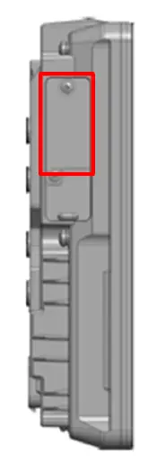
To download and upgrade the display program, please loosen the screw of the metal cover plate on the left side of the display screen, connect the computer with the USB data cable, and download and upgrade the programming cable through the upper computer. The USB interface is also used for screen program debugging. The electrical connector must be equipped at the same time when purchasing the product. The recommended table is as follows:
| No. | Name | Model | Illustration | manufacturer |
|
1 |
Amp connector socket sheath |
4-1437290-0 | 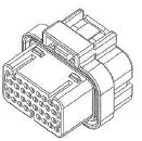 |
Tyco Electronics |
| 2 | AMP Connector metal pin | 3-1447221-3 | 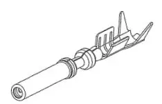 | Tyco Electronics |
Software development platform
It supports QT configuration software, adopts standard ide development environment, and can develop QT application program according to project requirements. Can refer to the commonly used sample programs, rapid development of applications. include:
- QuickStart human-machine interface, including common man-machine operation control
- QT-based communication function library, including can communication, 4G communication, GPS communication, BLE communication。
Program burning
QT application program burning
- Create app folder under the root directory of U disk and place QT configuration program
- The USB flash disk is connected to the USB port behind the display screen. When the main board is powered on, the display screen will pop up the configuration selection, click “burn”, the U disk indicator light starts to flash, and the burning progress is displayed.
- after burning, the display screen will automatically restart to complete the burning without power off.
Kernel and device tree burning
- Connect the upper USB port and notebook behind the display screen through USB adapter
- Turn off the firewall of the laptop windows system.
- If the rndis network device cannot be recognized in the “Device Manager → network adapter”,
Please install and driver. 4) set IP (display IP) and server IP (computer IP) must be in the same network segment
- Set computer IP: 192.168.1.66
- Set the IP of the display screen: 192.168.1.62, which can not be modified by default
- Restart the display screen and enter the boot mode. Enter the command from the serial console: serverip 192.168.1.66 setenv ipaddr 192.168.1.62 saveenv.
- Create a folder on the desktop, put tftpd32.exe, kernel, and device tree in this directory,
- Open tftpd32.exe, select the “sever interface” option, and select native IP: 192.168.1.66
- Update the device tree and input the command run update on the serial console_ FDT
- Update the kernel, input the command of the serial console: run update_ kernel
Connection with an external controller
It is connected with external controller through CAN bus and supports CAN2.0B, CANopen, J1939 and other protocols.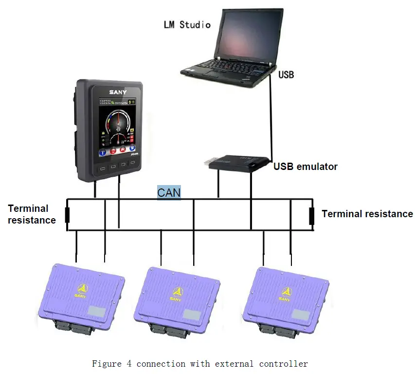
Description of product parameters and environmental indicators
| Number | Product name | Detailed |
| 1 | Video input | 4 channel,PAL / NTSC signal |
| 2 | 12V OUT | 2 channel |
|
3 |
Ø
Communication | CAN:2 channel,Rate selectable ISO11898 CAN2.0B、J1939、CanOpen; USB:1 channel,USB2.0; Support u disk upgrade program and U listen to songs and other functions 4G,Antenna built-in: LTE: B5/B41 GPS :Receive satellite’s longitude and latitude information bt : 1 channel,5m Communication (No obstacles) distance (barrier-free), receiving sensitivity: <-90 dBm, antenna built-in; EtherNet:1 channel,10/100/1000 Mbps |
|
4 |
Display | 7 inches Resolving power:800x 480 Industrial TFT LCD Screen Capacitive touch |
| 5 | Key | Quantity:1,HOME key |
|
6 |
Conventional parameters | Kernel: ARM Dual Core Main Frequency:1GHz DDR3 Memory:1GB Storage:8GB Power supply:DC 12-24V. (Recommended voltage DC 24 V ) Note: If the power supply voltage of video function should be > 14V, otherwise the camera can not be driven. Output voltage:DC 12V,1A Consumption current:0.55A(DC 24 V) Power waste:≤ 14W Video Display: Picture in Picture, 4 Segments/Single Picture |
|
7 |
Work environment | working temperature:- 20 ~ 65 °C Storage temperature:- 25 ~ 80 °C Overvoltage protection:37.2 V Anti vibration:4 – 300 Hz 10mm 5G Impact resistance:50G 6ms & 11ms Relative temperature:10 % ~ 95 % Protection level:IP 65 |
| 8 | Outline size | 197×131.5×48.9(mm |
Operating instructions
Bluetooth:
Turn on and find the Bluetooth logo in the main interface, click to enter, turn on the switch, Search the device, and you can connect to use.
4G:
Plug in the SIM flow card and the traffic will be turned on by default after power on, and you can use it. Upload the data to the remote monitoring center; receive the data from the monitoring center,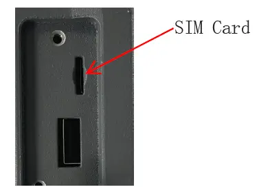
GPS:
After power is on, the GPS function is automatically turned on to determine the location of the device.
FM:
Turn on and find the Music logo in the main interface, click to enter, Select Radio, Select or switch the channel, you can use it directly.
FCC Statement
Any changes or modifications not expressly approved by the party responsible for compliance could void the user’s authority to operate the equipment. This device complies with part 15 of the FCC Rules. Operation is subject to the following two conditions: (1) This device may not cause harmful interference,and (2) this device must accept any interference received, including interference that may cause undesired operation.
FCC Radiation Exposure Statement:
This equipment complies with FCC radiation exposure limits set forth for an uncontrolled environment. This equipment should be installed and operated with minimum distance 20cm between the radiator& your body.
Note:
This equipment has been tested and found to comply with the limits for a Class B digital device, pursuant to part 15 of the FCC Rules. These limits are designed to provide reasonable protection against harmful interference in a residential installation. This equipment generates uses and can radiate radio frequency energy and, if not installed and used in accordance with the instructions, may cause harmful interference to radio communications. However,there is no guarantee that interference will not occur in a particular installation. If this equipment does cause harmful interference to radio or television reception, which can be determined by turning the equipment off and on, the user is encouraged to try to correct the interference by one or more of the following measures:
- Reorient or relocate the receiving antenna.
- Increase the separation between the equipment and receiver.
- Connect the equipment into an outlet on a circuit different from that to which the receiver is connected.
- Consult the dealer or an experienced radio/TV technician for help.


