ROSEN 111728 32 Inch 4K UHD Smart Display
Technical Manual, 4K UHD Displays
© 2022 by Rosen Aviation, LLC
All Rights Reserved The information contained herein is proprietary to Rosen Aviation, LLC. No part of this publication may be reproduced, transmitted, transcribed, stored in a retrieval system, or translated into any language in any form by any means without the written authorization from Rosen Aviation, LLC, except as allowed under copyright laws.
INTRODUCTION
This manual provides installation guidance and references to all technical information required to install, service and maintain the Rosen 4K UHD Displays.
System Overview
The Rosen 4K Displays offer an all-in-one design which allows several installation options. Each display can be installed in flush mount and semi-proud orientations. The displays also accommodate a variety of input signals, resolutions and control capabilities allowing installation versatility.
Control Options
- External IR receiver
- RS232
- Ethernet
- USB
- WI-FI (if equipped)
Please see interface control document P/N 111727
Mating Connectors
Recommended mating connectors are listed on the 4K Display Outline and Installation Drawings.
LRU LIST
Table 1 Smart Display LRU List
| Monitor Model Number | AC/DC | LCD/OLED |
| 4KS220-002 | DC | OLED |
| 4KS240-002 | DC | LCD |
| 4KS270-002 | DC | OLED |
| 4KS320-003 | DC | OLED |
| 4KS320-004 | DC | LCD |
| 4KS430-002 | DC | LCD |
| 4KS480-001 | AC | OLED |
| 4KS550-001 | AC | OLED |
INSTALLATION GUIDELINES
Cooling and Ventilation
For venting requirements see Outline and Installation drawings.
Electrical Requirements
- Operational Voltage Range 18 to 32VDC (DC models)
- Operational Voltage Range 97 to 134 VAC 360 to 800 HZ (AC models)
For Max Current see Outline and Installation drawing for each display size.
Inputs and Connections
All Rosen Smart Displays use the following connections:
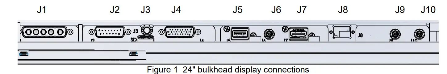
- Power (J1)
- I/O (J2)
- Wi-Fi (J3)
- Ethernet/strapping (J4)
- USB(J5)
- SPDIF (J6)
- HDMI (J7)
- Fiber optic (J8)
- SDI 1 (J9)
- SDI 2 (J10)
- SD Card (for future use)
Pinout Connections
There are several ways to connect the display to an aircraft’s entertainment system. Reference these pinout descriptions for the Smart Display Modules to assist in completing the wiring connections.
Note: This display is for entertainment purposes only; connect to a non-critical power bus.
Power Connector (J1) Pin-out Logic and Function
Table 2 Power Logic and Function for DC monitors
| Pin | Signal | Input/output | Description |
| A1 | PRIMARY 28VDC | Input | Aircraft power supply |
| A2 | PRIMARY RETURN | Input | Aircraft power supply |
| A3 | SECONDARY 28VDC | Input | Aircraft power supply |
| A4 | SECONDARY RETURN | Input | Aircraft power supply |
| A5 | Chassis | Chassis ground |
Table 3 Power Logic and Function for AC monitors
| Pin | Signal | Input/output | Description |
| A1 | Line 115 VAC | Input | Aircraft power supply |
| A2 | Earth (chassis) | Input | Aircraft power supply |
| A3 | Neutral 115 VAC | Input | Aircraft power supply |
I/O (J2) Pin-out Logic and Function
Table 4 I/O Logic and Function
| Pin | Signal | Input/output | Description |
| 1 | RESERVED | Reserved | Reserved |
| 2 | RESERVED | Reserved | Reserved |
| 3 | RESERVED | Reserved | Reserved |
| 4 | Signal GND | Output | Audio line out |
| 5 | Audio left | Output | Audio line out |
| 6 | Audio Right | Output | Audio line out |
| 7 | Audio mute control | Input | audio control |
| 8 | Select control | input | Video control |
| 9 | IR +5V | Output | 5 volts out |
| 10 | SIGNAL GND | ||
| 11 | RESERVED-Debug | Reserved | Reserved |
| 12 | IR in | input | IR signal input |
| 13 | Control RS232 TX | Output | RS232 Control |
| 14 | Control RS232 RX | Input | RS232 Control |
| 15 | Discrete out3 | Output | Reserved |
Wi-Fi Connector (J3) Pin-out Logic and Function
Table 5 Wi-Fi Logic and Function
| Pin | Signal | Input/output | Description |
| Center | Wi-Fi | Input/output | Wi-Fi input |
| Outer | Return | Input/output | Wi-Fi input |
No Wi-Fi on the 4KS320-004 monitor
Ethernet Connector (J4) Pin-out Logic and Function
Table 6 Ethernet Logic and Function
| Pin | Signal | Input/output | Description |
| 1 | ENET A+ (TX+) | Input/output | Gigabit Ethernet capable. TX+ for fast Ethernet (100baseT). |
| 2 | ENET A- (TX-) | Input/output | Gigabit Ethernet capable. TX- for fast Ethernet (100baseT). |
| 3 | ENET B+ (RX+) | Input/output | Gigabit Ethernet capable. RX+ for fast Ethernet (100baseT). |
| 4 | ENET B- (RX-) | Input/output | Gigabit Ethernet capable. RX- for fast Ethernet (100baseT). |
| 5 | ENET C+ | Input/output | Gigabit Ethernet capable. |
| 6 | ENET C- | Input/output | Gigabit Ethernet capable. |
| 7 | ENET D+ | Input/output | Gigabit Ethernet capable. |
| 8 | ENET D- | Input/output | Gigabit Ethernet capable. |
| 9 | Gb ENET Ctrl in | Input | Open = 100baseT, Ground = Gigabit |
| 10 | ETH_ADDR_0 | Input | This pin is used to set the IP address. See Ethernet Strapping for more information. |
| 11 | ETH_ADDR_1 | Input | This pin is used to set the IP address. See Ethernet Strapping for more information. |
| 12 | ETH_ADDR_2 | Input | This pin is used to set the IP address. See Ethernet Strapping for more information. |
| 13 | ETH_ADDR_3 | Input | This pin is used to set the IP address. See Ethernet Strapping for more information. |
| 14 | ETH_ADDR_4 | Input | This pin is used to set the IP address. See Ethernet Strapping for more information. |
| 15 | ETH_ADDR_5 | Input | This pin is used to set the IP address. See Ethernet Strapping for more information. |
| 16 | Power CTRL In | Input | See power mode section 4.1.5 |
| 17 | SDI CTRL in | Input | Open = fiber, Ground = Copper |
| 18 | SIGNAL GND | Typical return for strapping | |
| 19 | SIGNAL GND | Typical return for Ethernet strapping |
| Pin | Signal | Input/output | Description |
| 20 | RESERVED | Reserved | Reserved |
| 21 | RESERVED | Reserved | Reserved |
| 22 | RESERVED | Reserved | Reserved |
| 23 | RESERVED | Reserved | Reserved |
| 24 | RESERVED | Reserved | Reserved |
| 25 | RESERVED | Reserved | Reserved |
| 26 | USB-A OTG ID | Input | Open = USB Debug, Ground = USB normal use |
USB (J5) Pin-out Logic and Function
Table 7 USB Logic and Function
| Pin | Signal | Input/output | Description |
| 1 | VBUS | Output | +5 volt Power |
| 2 | USB D- | Input/output | USB 2.0 Data- |
| 3 | USB D+ | Input/output | USB 2.0 Data+ |
| 4 | GND | Ground | |
| 5 | SSRX- | Input | Super speed receiver |
| 6 | SSRX+ | Input | Super speed receiver |
| 7 | GND | Ground | |
| 8 | SSTX- | Output | Super speed Transmitter |
| 9 | SSTX+ | Output | Super speed Transmitter |
SPDIF Out (J6) Pin-out Logic and Function
Table 8 SPDIF Logic and Function
| Pin | Signal | Input/output | Description |
| Center | SPDIF | Output | SPDIF Audio Output |
| Outer | SPDIF Return | Output | SPDIF Audio Output |
HDMI (J7) Pin-out Logic and Function
Table 9 HDMI Logic and Function
| Pin | Signal | Input/output | Description |
| 1 | TMDS Data2+ | Input | |
| 2 | TMDS Data2 Shield | ||
| 3 | TMDS Data2− | Input | |
| 4 | TMDS Data1+ | Input | |
| 5 | TMDS Data1 Shield | ||
| 6 | TMDS Data1− | Input | |
| 7 | TMDS Data0+ | Input | |
| 8 | TMDS Data0 Shield | ||
| 9 | TMDS Data0− | Input | |
| 10 | TMDS Clock+ | Input | |
| 11 | TMDS Clock Shield | ||
| 12 | TMDS Clock− | Input | |
| 13 | CEC | Input/output | |
| 14 | Reserved | ||
| 15 | SCL | Input | I²C serial clock for DDC |
| 16 | SDA | Input/output | I²C serial data for DDC |
| 17 | Ground | Ground | |
| 18 | +5 V | Input | Power |
| 19 | Hot Plug Detect | Output |
Fiber Optic (J8) Pin-out Logic and Function
Table 10 Fiber Optic Logic and Function
| Pin | Signal | Input/output | Description |
| 1 | Ethernet 1 RX | Input | RX for Ethernet 1 |
| 2 | SDI-1 | Input | SDI video input 1 |
| 3 | Ethernet 2 RX | Input | RX for Ethernet 2 |
| 4 | SDI-2 | Input | SDI video input 2 |
| 5 | RESERVED | Reserved | Reserved |
| 6 | RESERVED | Reserved | Reserved |
| 7 | RESERVED | Reserved | Reserved |
| 8 | RESERVED | Reserved | Reserved |
| 9 | RESERVED | Reserved | Reserved |
| 10 | Ethernet 2 TX | Output | TX for Ethernet 2 |
| 11 | Reserved | Reserved | |
| 12 | Ethernet 1 TX | Output | TX for Ethernet 1 |
SDI Connectors (J9 and J10) Pin-out Logic and Function
Table 11 SDI Logic and Function
| Pin | Signal | Input/output | Description |
| Center | 3G-SDI | Input | SDI video input |
| Outer | 3G-SDI Return | Input | SDI video input |
Ethernet Strapping Setting the IP Address Mode in the Technician Settings to a static IP address will enable Ethernet Strapping. The table below describes the Ethernet pinout configuration for the 4K Display when the IP Address Mode is set to 10.0.0.100. The table shows the first eight entries, but the addressing range uses all 5 pins for a total of 64 addresses Reference the 4K Display Outline and Installation Drawing for the pin locations in the Ethernet & strapping connector.
Table 12 4K Display Ethernet Strapping
| IP Address | Ethernet Address Pins | Logic | |||||
| 5 | 4 | 3 | 2 | 1 | 0 | ||
| 10.0.0.100 | 0 | 0 | 0 | 0 | 0 | 0 | 0=GND 1=OPEN |
| 10.0.0.101 | 0 | 0 | 0 | 0 | 0 | 1 | 0=GND 1=OPEN |
| 10.0.0.102 | 0 | 0 | 0 | 0 | 1 | 0 | 0=GND 1=OPEN |
| 10.0.0.103 | 0 | 0 | 0 | 0 | 1 | 1 | 0=GND 1=OPEN |
| 10.0.0.104 | 0 | 0 | 0 | 1 | 0 | 0 | 0=GND 1=OPEN |
| 10.0.0.105 | 0 | 0 | 0 | 1 | 0 | 1 | 0=GND 1=OPEN |
| 10.0.0.106 | 0 | 0 | 0 | 1 | 1 | 0 | 0=GND 1=OPEN |
| 10.0.0.107 | 0 | 0 | 0 | 1 | 1 | 1 | 0=GND 1=OPEN |
Pre-installation
- All required Rosen products are complete and available.
- Aircraft geometry as well as fastener locations have been manufactured within the tolerances defined in the Rosen Outline and Installation drawings.
Installation
The Following equipment is necessary to complete the installation.
Note: Installation assumes Aircraft interior has been designed and fabricated using mating dimensions provided on the Outline and Installation drawing.
- Customer supplied fasteners
- Tooling required for customer supplied aircraft hardware installation For part details see Outline and Installation drawing.
- Monitor designed for rear mounting see Outline and Installation drawing
Software upgrade
The 4K displays support field upgrade via Ethernet/USB which is detailed in P/N 110231 or 111727.
INITIAL POWER UP
Make sure that power is turned off and perform the following steps.
- Ensure a low impedance ground connection on the chassis from the ground lug bosses indicated on the Outline and Installation drawing(optional).
- Connect the power supply and video source to the appropriate connectors.
- Supply power and wait for a video signal on the screen. The primary input is SDI
![]() Do not plug or unplug the display connector while power is applied. When cycling power, leave unit off for 20 seconds before restoring power.
Do not plug or unplug the display connector while power is applied. When cycling power, leave unit off for 20 seconds before restoring power.
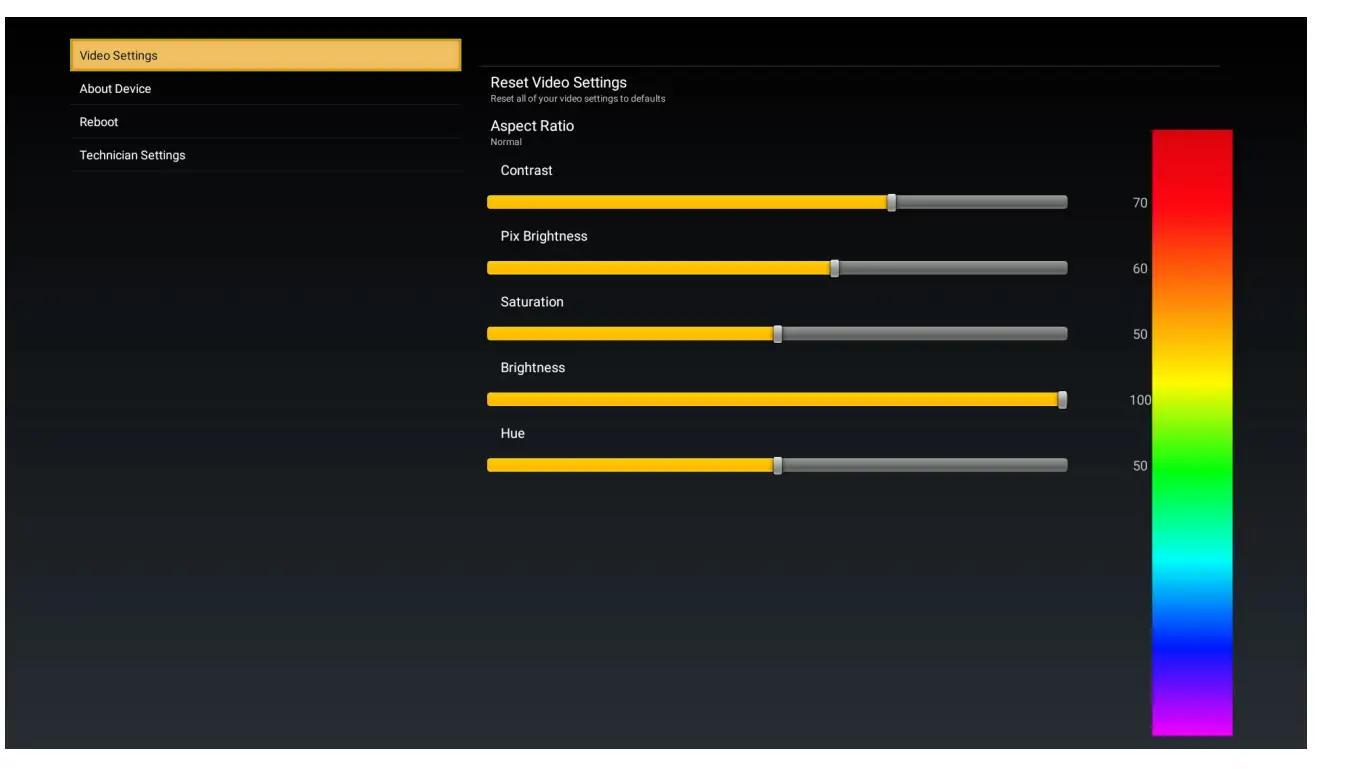
Video Settings
Reset video settings: use to reset to factory settings
Aspect Ratio: the Following are available
- Normal – scale the video image horizontally to fit the width of the screen
- Full screen- scale video horizontally & vertically until input image fills the screen
- Pillar box – create vertical bars on the right and left of the displayed image
- Stretch – stretch the video image to fit the height and width of the screen
Contrast: Adjust picture contrast
Pix Brightness: Adjust picture brightness
Saturation: Adjust picture Saturation
Brightness: Adjust brightness
Hue: Adjust picture hue
Motion Compensation: *enable or disable (only present on certain models)
About Device: Gives user Information about the monitor
Reboot: Reboots the device so you don’t need to pull power
Legal and regulatory: FCC info and rules
Technical settings
To protect the display from accidental or unintentional adjustments, the Technical Menu is accessible only with a special button combination. Changes made in the Technical Menu will take effect immediately, with the exception of Power Modes and IP settings. Power mode changes will take effect when the OSD is exited. IP Settings will take effect when the unit is rebooted.
To access the Technical Menu use the remote and quickly input the following with the arrow keys:
▲▼▲▼▲▲▲
The Technical Menu will pop up below the Legal & Regulatory. The following can be adjusted in the Technical Menu.
Remote Control Number: This allows you to change the remote ID 1-4 for use with Rosen’s programmable remote.
Power Mode: Allows you to modify how power input pin 16 of the J4 connector is used. The following are available: Auto on (default), Auto off, Ground on, Open on, or Momentary ground.
Mute Mode: Allows you to modify how audio is muted from input pin 7 of the J2 connector is used. The following are available: Ground on, Open on, or Momentary on
Reset all setting: This will reset everything to the default mode.
Video Over scan: This is for over scanning of SDI video, the default is 25 which is 2.5%
Device Alias: This allows you to name your device. This helps when multiple devices are on the same network.
Launcher Wallpaper: Selects a Wallpaper. Supported wallpaper formats: BMP JPEG, GIF, and PNG Select Boot Animation: Selects the animation shown during the boot process. Supports the Android-style .zip format
IP Address Mode: Choose between DHCP or specify a static IP address to use as the base of a range that takes strapping pins into account
Set Gateway IP Address: Lets you change the gateway IP Address.
Set Netmask IP Address: Lets you change the Netmask IP Address. Set DNS IP Address: Lets you change the DNS IP Address.
Source Mode: Allows you to modify how Video is selected from input pin 8 of the J2 connector is used. The following are available: auto and Manual.
Note: when in manual mode the IR function like the select in pin every momentary/source press cycle to the next enabled source.
EXT_HDMI: Allows you to enable/disable the source and prioritize if in auto mode
SDI 1: Allows you to enable/disable the source and prioritize if in auto mode
SDI 2: Allows you to enable/disable the source and prioritize if in auto mode
IMX8: this is the settings menu it cannot be disabled.
Start Pixel Refresh (OLED only): Mitigates, but does not prevent image burn-in. Monitor goes black during the process, which can take up to 1 hour and 15 minutes. Monitor picture will return when process is complete. Note: Part numbers 4KS220-002, 4KS270-002 and 4KS320-003 utilize a pixel wobble function to mitigate burn-in and image retention. This function runs continuously while the display is powered ON. There is no pixel refresh cycle available on these displays.
Wi-Fi : Allows you to enable/disable the Wi-Fi
Available Networks: Allows you to choose wi-fi network
UPLOADING USER CONTENT
User content consists of, Wallpaper and Animation Configure file structure below on USB
RosenConfigFiles
- Wallpapers (Supported wallpaper formats: BMP JPEG, GIF, and PNG)
- Boot Animations (Supports Android-style .zip formats)
Once the media files are appropriately organized, plug the USB drive into a monitor and follow on screen instructions. Files can also be transferred via network update, contact Rosen Aviation for additional information.
Troubleshooting
Table 13 Troubleshooting tips and solutions
| Problem | Possible Solutions |
| Screen is black |
|
Cleaning the Display
If glass surfaces become contaminated, surfaces may be cleaned by wiping with a microfiber cloth. The cloth may be dampened (but not wet) with deionized water. Do not spray water directly on the monitor or glass.
RTCA DO-160G Qualifications for Displays
The table below shows the DO-160G compliance of the 4K UHD Display, unless otherwise noted. Omitted test sections/categories are not applicable to this product or its expected installation.
Table 14 The UHD displays are tested to the following DO-160G test categories
P/N 4KS240-002, 4KS320-004 and 4KS430-002
| Description | Section | Category | Comments |
| Temperature and Altitude | 4 | ||
| Ground Survival/Short-Time Operating Low Temp | 4.5.1 | A1 | |
| Operating Low Temperature | 4.5.2 | A1 | |
| Ground Survival/Short-Time Operating High Temp | 4.5.3 | A1 | |
| Operating High Temperature | 4.5.4 | A1 | |
| In-Flight Loss of Cooling | 4.5.5 | – | Not Applicable |
| Altitude | 4.6.1 | A1 | +17,000ft |
| Decompression | 4.6.2 | A1 | Not Applicable |
| Overpressure | 4.6.3 | A1 | Not Applicable |
| Temperature Variation | 5 | ||
| Temperature Variation | 5.3.1 | C | -15°C to +55°C |
| Humidity | 6 | ||
| Standard Humidity | 6.3.1 | A | |
| Operational Shocks & Crash Safety | 7 | ||
| Operational Shocks | 7.2.2 | B | |
| Crash Safety (Impulse) | 7.3.2 | B | |
| Crash Safety (Sustained): Fixed-Wing Transport Aircraft, Random Orientation (≥9g/direction) | 7.3.3 | B | Satisfies Inertial Loads requirements per 14 CFR § 25.561(b)(3) |
| Vibration | 8 | ||
| Random Vibration – Fixed Wing Aircraft | 8.5.2 | S (Curve B) | |
| Waterproofness | 10 | Y | Substantiation by Company Testing |
| Fluids Susceptibility | 11 | ||
| Fluids Spray – Coffee, OJ, Cola, Cleaning Solvent (for all), Wine (for 32” and 43” only) | 11.4.1 | F | |
| Fungus Resistance | 13 | F | Substantiation by Analysis |
| Magnetic Effect | 15 | ||
| Magnetic Effect | 15.3 | B | Deflection Distance: D < 300 cm |
| Description | Section | Category | Comments |
| Power Input (DC, Designation ZXI) | 16 | ||
| Normal Operating Conditions (DC) | 16.6.1 | ||
| Average Value Voltage (DC) | 16.6.1.1 | Z | |
| Ripple Voltage (DC) | 16.6.1.2 | Z | |
| Momentary Power Interruptions (DC) | 16.6.1.3 | Z(A) | |
| Normal Surge Voltage (DC) | 16.6.1.4 | Z | |
| Engine Starting Under Voltage Operation (DC) | 16.6.1.5 | Z | |
| Abnormal Operating Conditions | 16.6.2 | ||
| Voltage Steady State (DC) | 16.6.2.1 | Z | |
| Low Voltage Conditions | 16.6.2.2 | – | |
| Momentary Under Voltage (DC) | 16.6.2.3 | Z | |
| Abnormal Surge Voltage (DC) | 16.6.2.4 | Z | |
| Inrush Current | 16.7.5 | I | |
| Voltage Spike | 17 | ||
| Voltage Spike | 17.4 | A | |
| Audio Frequency Susceptibility | 18 | ||
| AF Conducted Susceptibility- Power Inputs | 18.3.1 | Z | |
| Induced Signal Susceptibility | 19 | ||
| Magnetic Fields Induced Into Equipment | 19.3.1 | AC | |
| Electric Fields Induced into Equipmen | 19.3.2 | – | Not applicable to equipment with metal enclosure |
| Magnetic Fields Induced Into Interconnecting Cables | 19.3.3 | AC | |
| Electric Fields Induced Into Interconnecting Cables | 19.3.4 | AC | |
| Spikes Induced Into Interconnecting Cables | 19.3.5 | AC | |
| Radio Frequency Susceptibility | 20 | ||
| Conducted Susceptibility (CS) – 10 kHz to 400 MHz | 20.4 | T | |
| Radiated Susceptibility (RS) – 100 MHz to 8 GHz | 20.5 | T | |
| Emission of Radio Frequency Energy | 21 | ||
| Conducted RF Emission – 150 kHz – 152 MHz | 21.4 | M | |
| Radiated RF Emission – 100 MHz – 6 GHz | 21.5 | M | |
| Description | Section | Category | Comments |
| Electrostatic Discharge (ESD) | 25 | ||
| Electrostatic Discharge (ESD) | 25.5 | A | |
| Flammability | 26 | – | Flammability compliance per 14 CFR § 25.853 |
Table 15 The UHD OLED displays are tested to the following DO-160G test categories
P/N 4KS480-001 & 4KS550-001
| Description | Section | Category | Comments |
| Temperature and Altitude | 4 | ||
| Ground Survival/Short-Time Operating Low Temp | 4.5.1 | A1 | |
| Operating Low Temperature | 4.5.2 | A1 | |
| Ground Survival/Short-Time Operating High Temp | 4.5.3 | A1 | |
| Operating High Temperature | 4.5.4 | A1 | |
| In-Flight Loss of Cooling | 4.5.5 | – | Not Applicable |
| Altitude | 4.6.1 | F1 | +17,000ft |
| Decompression | 4.6.2 | A1 | Not Applicable |
| Overpressure | 4.6.3 | A1 | Not Applicable |
| Temperature Variation | 5 | ||
| Temperature Variation | 5.3.1 | C | -15°C to +55°C |
| Humidity | 6 | ||
| Standard Humidity | 6.3.1 | A | |
| Operational Shocks & Crash Safety | 7 | ||
| Operational Shocks | 7.2.2 | B | |
| Crash Safety (Impulse) | 7.3.2 | B | |
| Crash Safety (Sustained): Fixed-Wing Transport Aircraft, Random Orientation (≥9g/direction) | 7.3.3 | B | Satisfies Inertial Loads requirements per 14 CFR § 25.561(b)(3) |
| Vibration | 8 | ||
| Random Vibration – Fixed Wing Aircraft | 8.5.2 | S (Curve B) | |
| Waterproofness | 10 | Y | Substantiation by Company Testing |
| Fluids Susceptibility | 11 | ||
| Fluids Spray – Coffee, OJ, Cola, Cleaning Solvent (for all), Wine (for 32” and 43” only) | 11.4.1 | N/A | |
| Fungus Resistance | 13 | F | Substantiation by Analysis |
| Description | Section | Category | Comments |
| Magnetic Effect | 15 | ||
| Magnetic Effect | 15.3 | B | Deflection Distance: D < 300 cm |
| Power Input | 16 | ||
| Variable Electrical power input parameters | 16.5 | ||
| Average Value Voltage (AC) | 16.5.1.1 | A(WF) | |
| Voltage Modulation (AC) | 16.5.1.2 | A(WF) | |
| Frequency Modulation (AC) | 16.5.1.3 | A(WF) | |
| Momentary Power Interruptions (AC) | 16.5.1.4 | A(WF) | |
| Normal Surge Voltage (AC) | 16.5.1.5.1 | A(WF) | |
| Normal Frequency Transients (AC) | 16.5.1.5.2 | A(WF) | |
| Normal Frequency Variations (AC) | 16.5.1.6 | A(WF) | |
| Voltage DC Content (AC) | 16.5.1.7 | A(WF) | |
| Voltage Distortion (AC) | 16.5.1.8 | A(WF) | |
| Abnormal Voltage and Frequency Limits in Steady State (AC) | 16.5.2.1 | A(WF) | |
| Momentary Undervoltage Operations (AC) | 16.5.2.2 | A(WF) | |
| Abnormal Surge Voltage (AC) | 16.5.2.3.1 | A(WF) | |
| Abnormal Frequency Transients (AC) | 16.5.2.3.2 | A(WF) | |
| Abnormal Frequency Variations (AC) | 16.5.2.3.3 | A(WF) | |
| Abnormal Frequency Variations (AC) | 16.7 | ||
| DC Current Content in Steady-State Operation (AC) | 16.7.3 | A(WF) | |
| Inrush Current (AC) | 16.7.5 | X | Report Levels Only |
| Current Modulation in Steady-State Operation (AC) | 16.7.6 | L | |
| Power Factor (AC) | 16.7.8 | P | |
| Voltage Spike | 17 | ||
| Voltage Spike | 17.4 | A | |
| Audio Frequency Susceptibility | 18 | ||
| Audio Frequency Conducted Susceptibility – Power Inputs | 18.3.2 | R(WF) | |
| Induced Signal Susceptibility | 19 | ||
| Magnetic Fields Induced Into Equipment | 19.3.1 | AW | |
| Electric Fields Induced into Equipment | 19.3.2 | – | Not applicable to equipment with metal enclosure |
| Description | Section | Category | Comments |
| Magnetic Fields Induced Into Interconnecting Cables | 19.3.3 | AW | |
| Electric Fields Induced Into Interconnecting Cables | 19.3.4 | AW | |
| Spikes Induced Into Interconnecting Cables | 19.3.5 | AW | |
| Radio Frequency Susceptibility | 20 | ||
| Conducted Susceptibility (CS) – 10 kHz to 400 MHz | 20.4 | T | |
| Radiated Susceptibility (RS) – 100 MHz to 8 GHz | 20.5 | T | |
| Emission of Radio Frequency Energy | 21 | ||
| Conducted RF Emission – 150 kHz – 152 MHz | 21.4 | M | |
| Radiated RF Emission – 100 MHz – 6 GHz | 21.5 | M | |
| Electrostatic Discharge (ESD) | 25 | ||
| Electrostatic Discharge (ESD) | 25.5 | A | |
| Flammability | 26 | C | Flammability compliance per 14 CFR § 25.853 |
Table 16 The UHD JOLED displays are tested to the following DO-160G test categories
P/N 4KS220-002, 4KS270-002 and 4KS320-003
| Description | Section | Category | Comments |
| Temperature and Altitude | 4 | ||
| Ground Survival/Short-Time Operating Low Temp (-30/-20°C) | 4.5.1 | A4 | |
| Operating Low Temperature (-15°C) | 4.5.2 | A4 | |
| Ground Survival/Short-Time Operating High Temp (60/50°C) | 4.5.3 | A4 | |
| Operating High Temperature (45°C) | 4.5.4 | A4 | |
| In-Flight Loss of Cooling | 4.5.5 | – | Not Applicable |
| Altitude | 4.6.1 | A4 | +17,000ft |
| Decompression | 4.6.2 | A4 | Not Applicable |
| Overpressure | 4.6.3 | A4 | Not Applicable |
| Temperature Variation | 5 | ||
| Temperature Variation | 5.3.1 | C | -15°C to +55°C |
| Humidity | 6 | ||
| Standard Humidity | 6.3.1 | A | |
| Description | Section | Category | Comments |
| Operational Shocks & Crash Safety | 7 | ||
| Operational Shocks | 7.2.2 | B | |
| Crash Safety (Impulse) | 7.3.2 | B | |
| Crash Safety (Sustained): Fixed-Wing Transport Aircraft, Random Orientation (≥9g/direction) | 7.3.3 | B | Satisfies Inertial Loads requirements per 14 CFR § 25.561(b)(3) |
| Vibration | 8 | ||
| Random Vibration – Fixed Wing Aircraft | 8.5.2 | S (Curve B) | |
| Waterproofness | 10 | Y | |
| Fluids Susceptibility | 11 | ||
| Fluids Spray – Coffee, OJ, Cola, Cleaning Solvent | 11.4.1 | – | |
| Fungus Resistance | 13.5 | F | Substantiation by Analysis |
| Magnetic Effect | 15 | ||
| Magnetic Effect | 15.3 | Z | Deflection Distance: D < 30 cm |
| Power Input (DC, Designation ZXI) | 16 | ||
| Normal Operating Conditions (DC) | 16.6.1 | ||
| Average Value Voltage (DC) | 16.6.1.1 | Z | |
| Ripple Voltage (DC) | 16.6.1.2 | Z | |
| Momentary Power Interruptions (DC) | 16.6.1.3 | Z (A) | |
| Normal Surge Voltage (DC) | 16.6.1.4 | Z | |
| Engine Starting Under Voltage Operation (DC) | 16.6.1.5 | Z | |
| Abnormal Operating Conditions | 16.6.2 | ||
| Voltage Steady State (DC) | 16.6.2.1 | Z | |
| Low Voltage Conditions | 16.6.2.2 | – | |
| Momentary Under Voltage (DC) | 16.6.2.3 | Z | |
| Abnormal Surge Voltage (DC) | 16.6.2.4 | Z | |
| Inrush Current | 16.7.5 | I | |
| Voltage Spike | 17 | ||
| Voltage Spike | 17.4 | A | |
| Audio Frequency Susceptibility | 18 | ||
| AF Conducted Susceptibility- Power Inputs | 18.3.1 | Z | |
| Induced Signal Susceptibility | 19 | ||
| Magnetic Fields Induced Into Equipment | 19.3.1 | AC | |
| Description | Section | Category | Comments |
| Electric Fields Induced into Equipment | 19.3.2 | – | Not applicable to equipment with metal enclosure |
| Magnetic Fields Induced Into Interconnecting Cables | 19.3.3 | AC | |
| Electric Fields Induced Into Interconnecting Cables | 19.3.4 | AC | |
| Spikes Induced Into Interconnecting Cables | 19.3.5 | AC | |
| Radio Frequency Susceptibility | 20 | ||
| Conducted Susceptibility (CS) – 10 kHz to 400 MHz | 20.4 | T | |
| Radiated Susceptibility (RS) – 100 MHz to 8 GHz | 20.5 | T | |
| Emission of Radio Frequency Energy | 21 | ||
| Conducted RF Emission – 150 kHz – 152 MHz | 21.4 | M | |
| Radiated RF Emission – 100 MHz – 6 GHz | 21.5 | M | |
| Electrostatic Discharge (ESD) | 25 | ||
| Electrostatic Discharge (ESD) | 25.5 | A | |
| Flammability | 26 | C | Flammability compliance per 14 CFR § 25.853 |
Supported Video Specifications
3G-SDI Resolutions
480i/29.97
576i/25
720p/50, 720p/59.94, 720p/60
1080i/25, 1080i/29.97, 1080i/30
1080p/23.97, 1080p/24, 1080p/25, 1080p/29.97, 1080p/30, 1080p/50, 1080p/59.94,
1080p/60
3G-SDI 4K UHD Resolutions
3840×2160/23.97, 3840×2160/24, 3840×2160/25, 3840×2160/29.97, 3840×2160/30, 3840×2160/50, 3840×2160/59.94, 3840×2160/60
HDMI resolutions
480i/29.97, 480i/30
576i/25
480p/59.94, 480p/60
576p/50
720p/50, 720p/59.94, 720p/60
1080i/25, 1080i/29.97, 1080i/30
1080p/23.97, 1080p/24, 1080p/25, 1080p/29.97, 1080p/30, 1080p/50, 1080p/59.94,
1080p/60
3840×2160/23.97, 3840×2160/24, 3840×2160/25, 3840×2160/29.97, 3840×2160/30,
3840×2160/50, 3840×2160/59.94, 3840×2160/60
HDR10 & HLG compatible
HDCP 1.4 & HDCP 2.2 compatible
![]() OLED displays are susceptible to screen burn-in and image retention. Avoid prolonged usage of static imagery such as banners, menus and logos.
OLED displays are susceptible to screen burn-in and image retention. Avoid prolonged usage of static imagery such as banners, menus and logos.
* *For this reason, the display has built in protective features to automatically reduce the brightness of the panel during elevated temperatures or when a static image is detected for extended periods of time. Rosen also employs a pixel refresh cycle that can reduce and eliminate the effects of burn-in and image retention. The panel manufactuer recommends this function only be used when burn-in or image retention is clearly present. The pixel refresh cycle is only accessible in the display Technicians Menu.”
DEFINITIONS
3G-SDI Newer, high-definition serial digital interface with a single 2.970 Gbit/s serial link
LRU Line Replaceable Unit
LCD Liquid Crystal Display
P/N Part Number
RS-232 Standard for serial data communication lines
VDC Volts direct current
REVISION HISTORY
![]() Revision E is limited to draft or prototype documents. Revisions I, O, Q, S, X and Z are not to be used.
Revision E is limited to draft or prototype documents. Revisions I, O, Q, S, X and Z are not to be used.
| Revision | Date | Revision Description | EC |
| A | 10-13-21 | Initial release | 21-0472 |
| B | 2-17-22 | Add Motion Compensation to Section 4.1.1. Add Start Pixel Refresh to Section 4.1.5. Add clarification to Notice in Section 5.4.3. | 22-0059 |
| C | 2-23-22 | Fixed table of contents | 22-0067 |
| D | 3-23-22 | Added Joleds and updated DO160 tables | 22-0113 |
CUSTOMER SUPPORT
Rosen Aviation, LLC
1020 Owen Loop South
Eugene, OR 97402
541.342.3802
888.668.4955
Fax: 541.342.4912
www.rosenaviation.com