![]()
SEID-3I0A(G) User manual
SEID-3I0A(G) User Manual V1.0
Functions and features
Special development environment
LM studio, a configuration software independently developed by RISING, has the following characteristics:
- Language model for embedded real-time control system development
- High security and confidentiality
- The modular structure is adopted
Short entry cycle, easy to use
Adapt to the harsh environment
- Can be used in a cold and hot environment: – 20 -C7 low temperature, 65 thigh temperature
- Anti-reverse connection design of power supply
- It is suitable for strong vibration, dusty rain, lightning, and another environment of field operation
Product appearance structure-function description
Product appearance

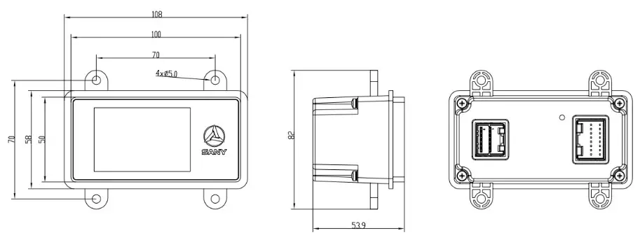
Product installation size
| NAME | FUNCTION | Pin | NOTE | |
| Analog input | Power input | AI 1.1 | J3-1 | Analog voltage AI_ V sampling: sampling range 0-10V DC, sampling accuracy 0.5%, resolution 0.025%; |
| AI_V_2 | J3-9 | |||
| Resistor input | AI R 1 | J2-10 | 0 2000, Accuracy 1% | |
| AI_R_2 | J2-13 | |||
| Digital output | PWM | PWM_1 | J3-3 | PWM output: frequency: 50 ‘‘’ 2kHz, current: 0 “” 2A, accuracy: 1%, resolution: 0.025%; |
| PWM_2 | J3-4 | |||
| PWM_3 | J3-5 | |||
| PWM_4 | J3-6 | |||
| DO | D0_1 | J2-5 | When output, the corresponding do is about the supply voltage; DC 1. 5A | |
| D0_2 | J2-14 | |||
| Digital input | DI_H/L | DI_H_l | J2-2 | The low-level effective threshold voltage (0 – 4.5V), high level the effective threshold voltage (5 – 36V) |
| DI_H_2 | J2-3 | |||
| DI_H_3 | J2-4 | |||
| DI_H_4 | J2-7 | |||
| DI_H_5 | J2-12 | |||
| DI_L_1 | J2-8 | |||
| DI_L_2 | 1211 | |||
| DI_L_3 | 1216 | |||
| Reset | Reset | J3-8 | Arm reset, power on and ground short circuit for 5S | |
| (IND | GND | J2-1, J3-7 | GND | |
| +5V output | +5VOUT | J3-2 | 5V±200mV power supply output,, Max output is300mA | |
| DC Input | +12VIn | J3-11,12 | Rating: 12V, range: 9V-16V | |
| communicate on | CAN | CAN H | J2-6 | There is no 120 inside Q Terminal resistance; |
| CAN_L | J2-15 | |||
Product parameters and environmental indicators
| NO. | NAME | Detail |
| Kernel | STM32F4291G ( 32 bit ARM ) | |
| Kernel frequency | 180MHz | |
| Working cycle | ≤ 5 ms | |
| CAN channel | 1. 15011898 CAN 2.08, 11939 | |
| Voltage input | 9 ∼16V.DC ( Recommended voltage 12V.DC ) | |
| Output | SV.DC. 300mA | |
| Current | 0.12A.DC ( 12V.DC) ( NO LOAD ) | |
| Power | ≤5W | |
| 9 | Working Temperature | -20 ∼ +65 r |
| 10 | Storage temperature | -25 ∼ +80 r |
| 1I | RS | 3V/m. 80MHz-661-1z |
| I9 | ESD | Air discharge ±8kV Contact discharge ±4kV |
| I | Anti-vibration level | 6.8g |
| II | Shock resistance | 50g. 6ms |
| 15 | Relative humidity | ≤95% |
| 16 | Dimensions | 108X82X54 (mm) |
| 17 | Weight | 0.23Kg |
NOTE
All the sensors, loads and other input and output points connected with the display screen must be connected into a closed-loop, that is, all the input and output ground must be connected with the corresponding ground of the controller.
FCC Statement:
Any changes or modifications not expressly approved by the party responsible for compliance could void the user’s authority to operate the equipment.
This device complies with part 15 of the FCC Rules. Operation is subject to the following two conditions: (1) This device may not cause harmful interference, and (2) this device must accept any interference received, including interference that may cause undesired operation.
FCC Radiation Exposure Statement:
This equipment complies with FCC radiation exposure limits set forth for an uncontrolled environment. This equipment should be installed and operated with a minimum distance 20cm between the radiator& your body.
Note: This equipment has been tested and found to comply with the limits for a Class B digital device, pursuant to part 15 of the FCC Rules. These limits are designed to provide reasonable protection against harmful interference in a residential installation. This equipment generates uses and can radiate radio frequency energy and, if not installed and used in accordance with the instructions, may cause harmful interference to radio communications. However, there is no guarantee that interference will not occur in a particular installation. If this equipment does cause harmful interference to radio or television reception, which can be determined by turning the equipment off and on, the user is encouraged to try to correct the interference by one or more of the following measures:
—Reorient or relocate the receiving antenna.
—Increase the separation between the equipment and receiver.
—Connect the equipment into an outlet on a circuit different from that to which the receiver is connected.
—Consult the dealer or an experienced radio/TV technician for help.


