![]() INSTRUCTION MANUAL
INSTRUCTION MANUAL
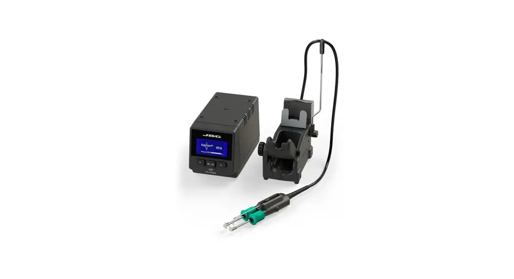
WSB
High-Temperature
Wire Stripper Station
This manual corresponds to the following references:
WSB-9A (100V)
WSB-1A (120V )
WSB-2A (230V)
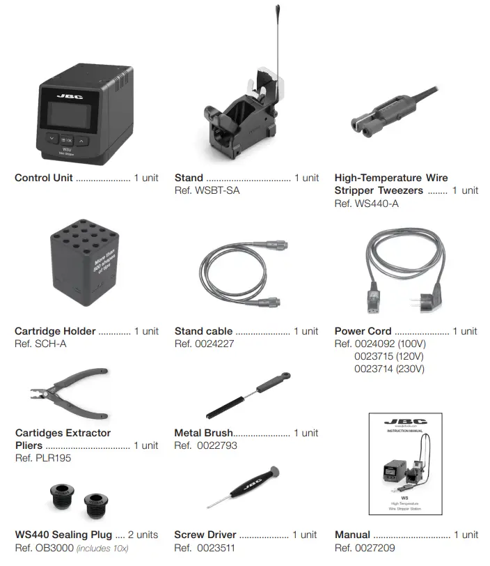
Packing List
The following items are included:
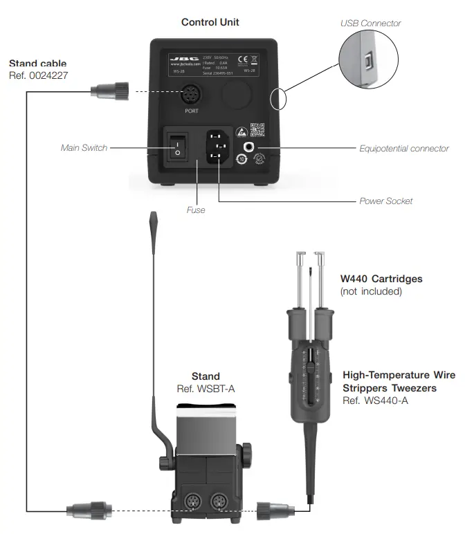
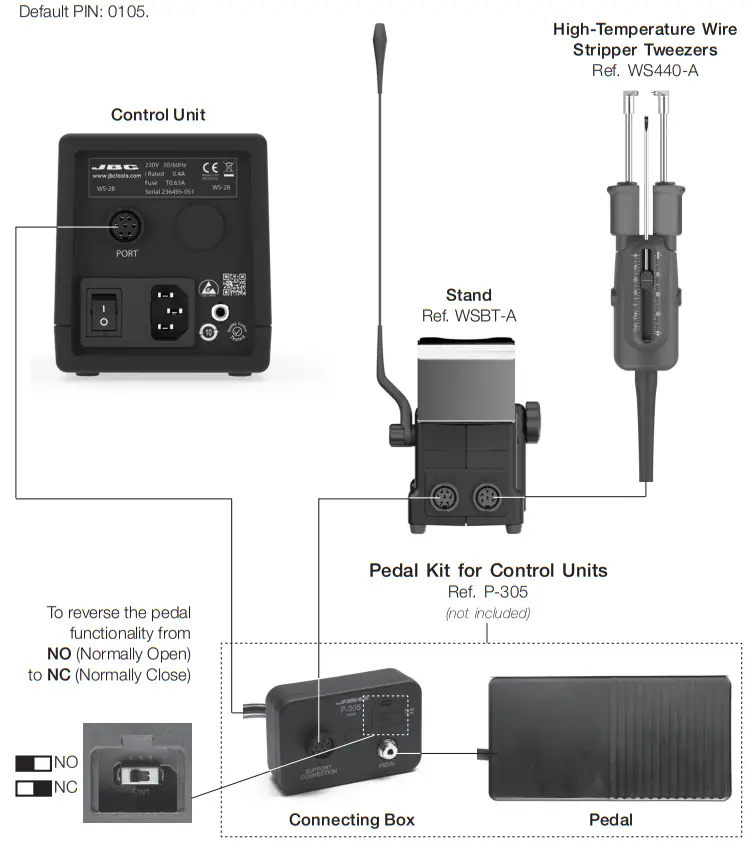
Features and Connections
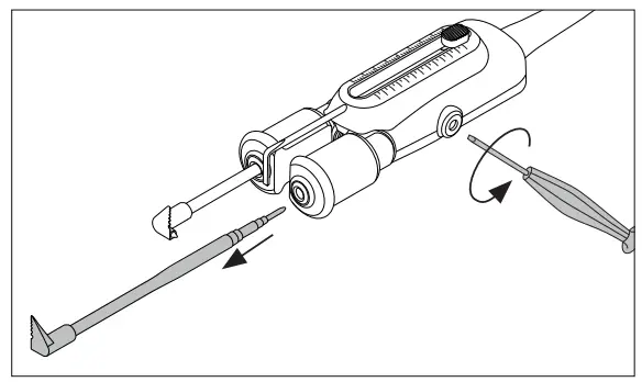
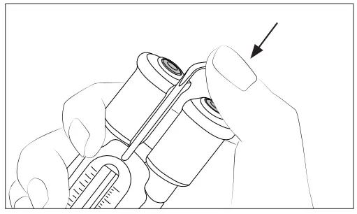
Changing Cartridges
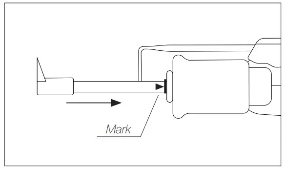
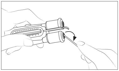
| 1. Removing Loosen the screws and remove the cartridges. | 2. Inserting Insert the cartridge until the reference mark. Take the mark as a reference and check that both tips match. Important: It is essential to insert the cartridge till the mark for a good connection. |
 |  |
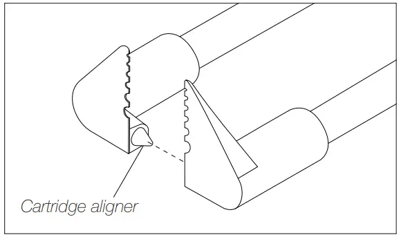
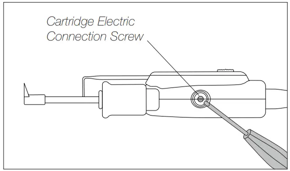
| 3. Positioning Align the cartridges in a working position using an fl at pliers (JBC Ref. PLR-195). The conical cartridge aligner helps center both cartridges and ensures good functionality. | 4. Fixing Fix the cartridges in their working position. by tightening the screw. Important: It is essential to tighten the screws for the tool to function. |
 |  |
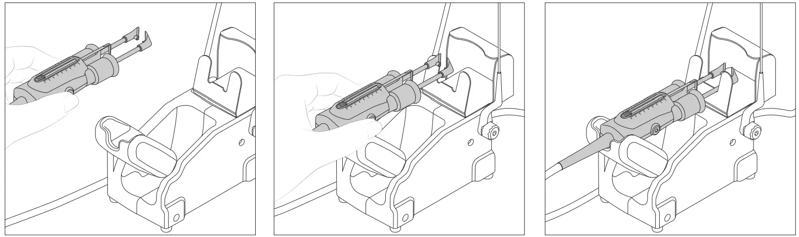
Stripping a Wire
| 1. Align Wire Place the wire touching the strip gauge. | 2. Close Cartridges Choose cartridges according to the wire diameter. Pinch the wire with the blades. The pinched area will be melted by heat. |
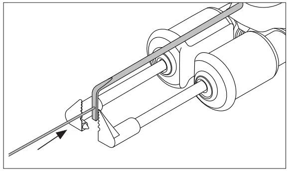 | 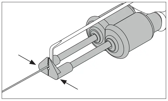 |
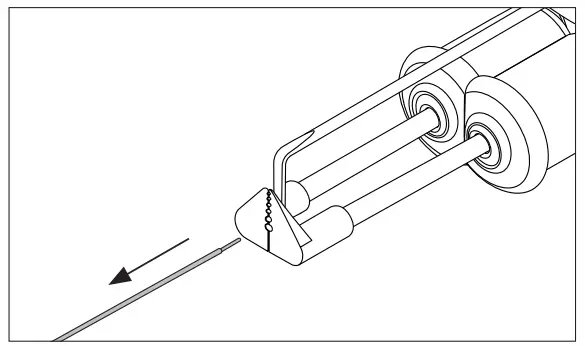 | 3. Remove Wire Pull the wire stripper toward to strip off the wire end. |
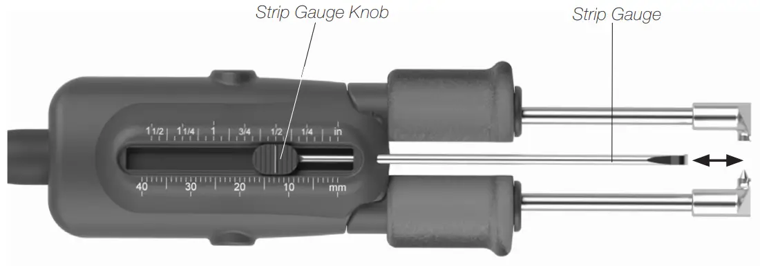
Adjustable Strip Gauge
Adjust the strip gauge according to your stripping requirements.
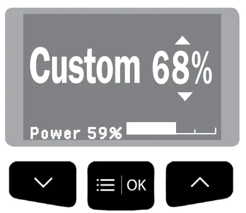
Control Process
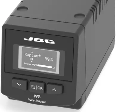
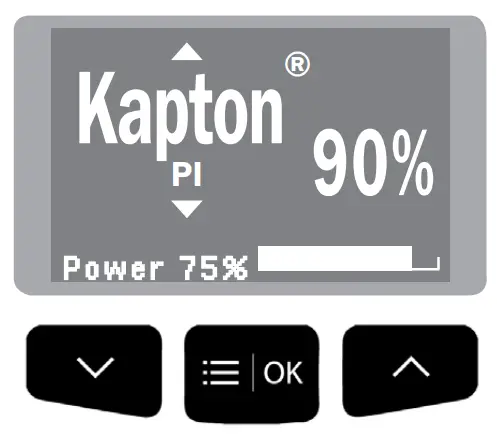
Work Screen
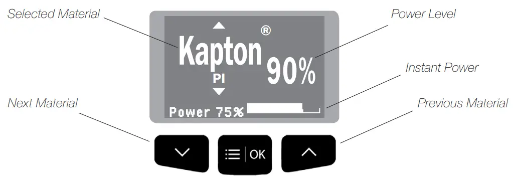
Work Mode
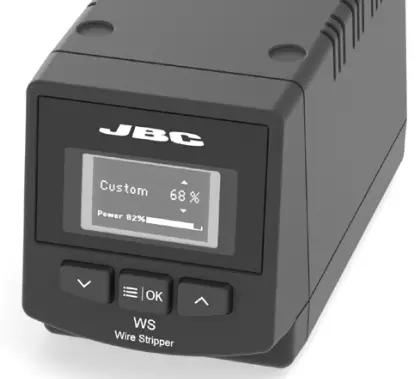
WSS offers two different working modes. Switch the power on choose between Material Mode and Custom Mode by pressing the ![]() button.
button.
| 1. Material Mode Choose between the different materials by pressing the buttons | 2. Custom Mode To work on a customized mode, press |
 |  |
 |  |
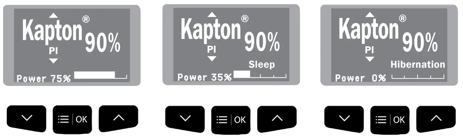
Operation
Depending on where the tool is located, the soldering station switches between three different statuses: Work, Sleep and Hibernation.
| 1. Work When the wire stripper is lifted from the stand, the cartridges will heat up according to the selected configuration. | 2. Sleep When the wire stripper is in the stand, the power falls after a specified time. | 3. Hibernation |
 | ||
 | ||
Troubleshooting
Station troubleshooting is available on the product page at www.jbctools.com
Material Mode
WSS incorporates predetermined power levels and it also features a customized work mode. It allows you to work on wire insulations made of thermoplastics and thermostable materials such as Tefl on1, Kapton2, silicone, rubber, etc.
Options included:
| Insulation Material | Symbol | Power Level | |
| Thermoplastics | Polyvinyl Chloride | PVC | 6% |
| Polyethylene | PE | 7% | |
| Nylon 1 | PA | 10% | |
| Kynar 2 | PVDF | 16% | |
| Tefzel 1 | ETFE | 17% | |
| Thermostable | Teflon 1 | FEB | 16% |
| PFA | 21% | ||
| PTFE | 40% | ||
| Ethylene Propylene Rubber | EPM/EPR | 44% | |
| Silicone Rubber | SI | 51% | |
| Kapton 1 | PI | 90% |
¹ Registered Trade Marks of DuPont
² Registred Trade Marks of Arkema
Cartridge Range
WS440-A is compatible with W440 Blade Cartridge Range. Find the model that best suits your soldering needs on www.jbctools.com.
If an application requires a special tip design, contact JBC by mail at [email protected].
| Cartridge Ref. | Tip Hole ø mm / in | AWG Stranded | AWG Solid | |
| W440021 | 0,16 / 0,0063 | 36 (7×44) | 34 | 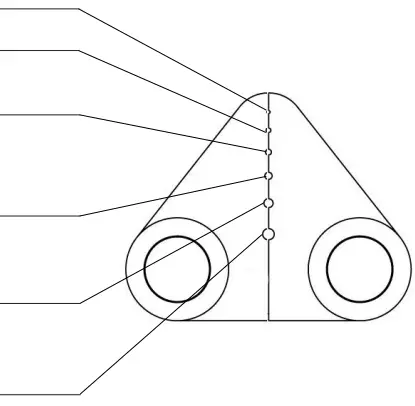 |
| 0,25 / 0,0098 | 32 (19×44) | 30 | ||
| 0,32 / 0,0126 | 30 (7×38) | 28 | ||
| 30 (19×42) | ||||
| 0,40 / 0,0157 | 28 (19×40 | 26 | ||
| 27 (7×35) | ||||
| 0,51 / 0,0201 | 26 (19×38) | 24 | ||
| 26 (10×36) | ||||
| 0,64 / 0,0252 | 24 (19×36) | 22 | ||
| 24 (7×32) | ||||
| W440023 | 0,40 / 0,0157 | 28 (19×40) | 26 | 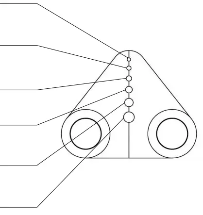 |
| 27 (7×35) | ||||
| 0,51 / 0,0201 | 26 (19×38) | 24 | ||
| 26 (10×36) | ||||
| 0,64 / 0,0252 | 24 (19×36) | 22 | ||
| 24 (7×32) | ||||
| 0,81 / 0,0319 | 22 (19×34) | 20 | ||
| 1,02 / 0,0402 | 20 (42×36) 20 (19×32) 20 (7×28) | 18 | ||
| 1,29 / 0,0508 | 18 (19×30) | 16 |
| Cartridge Ref. | Tip mm / in | 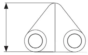 |
| W440025 | Flat Blade 12,5 / 0.4921 |
Sealing Plug Replacement
The Sealing Plug is meant to prevent undesirable flux vapors or particles from entering inside the tool.
Its usage is highly recommended for intensive applications when soldering is exposed to FOD environments or for applications where the soldering iron works close to a vertical position.![]() Before replacing the seal, unplug the power supply and make sure the device is not hot.
Before replacing the seal, unplug the power supply and make sure the device is not hot.
| 1. Removing Enter a small shaft or screwdriver in order to gently lift and pull the sealing plug. Do not insert the tool more than 8 mm deep. Never use a cartridge to do this operation. | 2. Mounting Note the sealing plug mounting position: The chamfered side has to be positioned towards the handle. |
 | 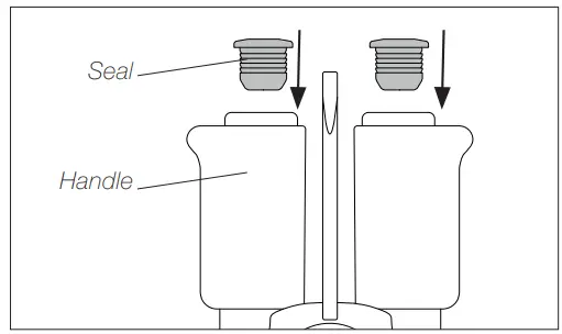 |
 | 3. Inserting Gently push the sealing plug inside the handle until it is completely into the handle. Handle and seal edges have to be aligned. |
Accessories
Flat Screw Driver*
To open or fi x the wire stripper crews use JBC Flat Screw Driver Ref. 0023511.

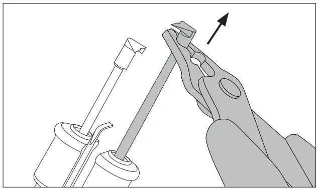
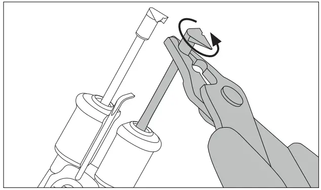
Cartridge Extractor Pliers*
To manipulate the cartridges use JBC Cartridge Extractor Pliers Ref. PLR195. More Information at www.jbctools.com

| Removing Remove cartriges with JBC pliers. | Inserting and Positioning Align cartridges with JBC pliers. |
 |  |
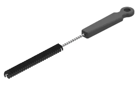
Metal Brush
For cleaning the tips if unwanted material is stuck there. Metal Brush Ref. 0022793.
Pedal Kit for Control Units
Pedal P305 can be used to activate/deactivate the Wire Stipper. Previously the Hibernation delay has to be set to 0 min.
Lift the wire stripper from the stand, press and hold the pedal to activate them and strip the wire.
Once the pedal is relaesed the wire stripper enters in Hibernation. To reverse the pedal functionality flip the switch of the connection box.
Maintenance
Before carrying out maintenance or storage, always allow the equipment to cool and unplug the stand from the station and the tool.
– Clean the station screen with a glass cleaner or a damp cloth.
– Use a damp cloth to clean the casing, the stand and the tool. Alcohol can only be used for cleaning the metal parts.
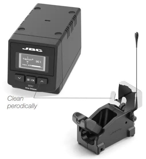
– Periodically check that the metal parts of the tool and stand are clean so that the station can detect the tool status.
– Maintain tip surface clean in order to ensure a correct stripped wire.
– Periodically check all cables.
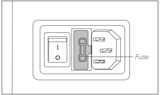
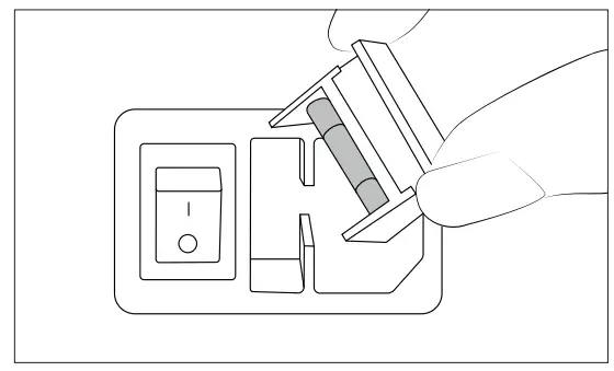
– Replace a blown fuse as follows (see specification chart) :
| 1. Pull off the fuse holder and remove the fuse. If necessary use a tool to lever it off. | 2. Press the new fuse into the fuse holder and replace it in the station. |
 |  |
– Replace any defective or damaged pieces. Use original JBC spare parts only.
– Repairs should only be performed by a JBC authorized technical service.
Safety
Warning
– Do not touch the blade or the metal parts arround.
– Do not allow the blade be close to flammable materials.
– Keep your workplace clean and tidy. Wear appropriate protection glasses and gloves when working to avoid personal harm.
– This appliance can be used by children over the age of eight and also persons with reduced physical, sensory or mental capabilities or lack of experience provided that they have been given adequate supervision or instruction concerning use of the appliance and understand the hazards involved.
– Maintenance must not be carried out by children unless supervised.
– Place the tool on the stand when is not in use.
– Turn off the power when not in use, changing parts or storing.
Caution
– Do not use the Wire Stripper for other applications than wire stripping.
– Do not modify or customize the Wire Stripper.
– Do not hit the blade against workbench to eliminate stripped insulation debris. This behavior would damage the blade.
– Remove power from the tool by holding the plug, not the wires.
– Be careful with the fumes produced when stripping. We recomend to use our fume extractor.
Specifications
WSB
High-Temperature Wire Stripper Station
Ref.: WSB-9A 100V 50/60Hz. Input Fuse: T1.6A. 5x20mm Output: 15V
Ref.: WSB-1A 120V 50/60Hz. Input Fuse: T1.25A. 5x20mm Output: 15V.
Ref.: WSB-2A 230V 50/60Hz. Input Fuse: T0.63A. 5x20mm Output: 15V.
| – Temperature Max : – Power: – Ambient operating temp: – Connections: – Control Unit Dimensions / Weight: (L x W x H) – Total Net Weight: – Total Package Dimensions / Weight: (L x W x H) | 800 ºC /1472 °F 75W 10 to 50 ºC /50 to 120 ºF USB-B 180 x 94 x 106 mm / 2.2 kg 7.1 x 3.7 x 4.2 in / 4.85 lb 3.8 kg / 8.4 lb 368 x 368 x 195 mm / 4.6 kg 14.5 x 14.5 x 7.7 in /10.15 l b |
![]()
Warranty
JBC’s 2 year warranty covers this equipment against all manufacturing defects, including the replacement of defective parts and labour.
Warranty does not cover product wear or misuse.
In order for the warranty to be valid, equipment must be returned, postage paid, to the dealer where it was purchased.
Get 1 extra year JBC warranty by registering here: https://www.jbctools.com/productregistration/ within 30 days of purchase.
![]() This product should not be thrown in the garbage.
This product should not be thrown in the garbage.
In accordance with the European directive 2012/19/EU, electronic equipment at the end of its life must be collected and returned to an authorized recycling facility
 www.jbctools.com
0027209-0621


hot Air Station Instruction Manual")
 Precision Hot Air Station Instruction Manual")
hot Air Station Extractor Desk Instruction Manual")
high Precision Hot Air Station Instruction Manual")


