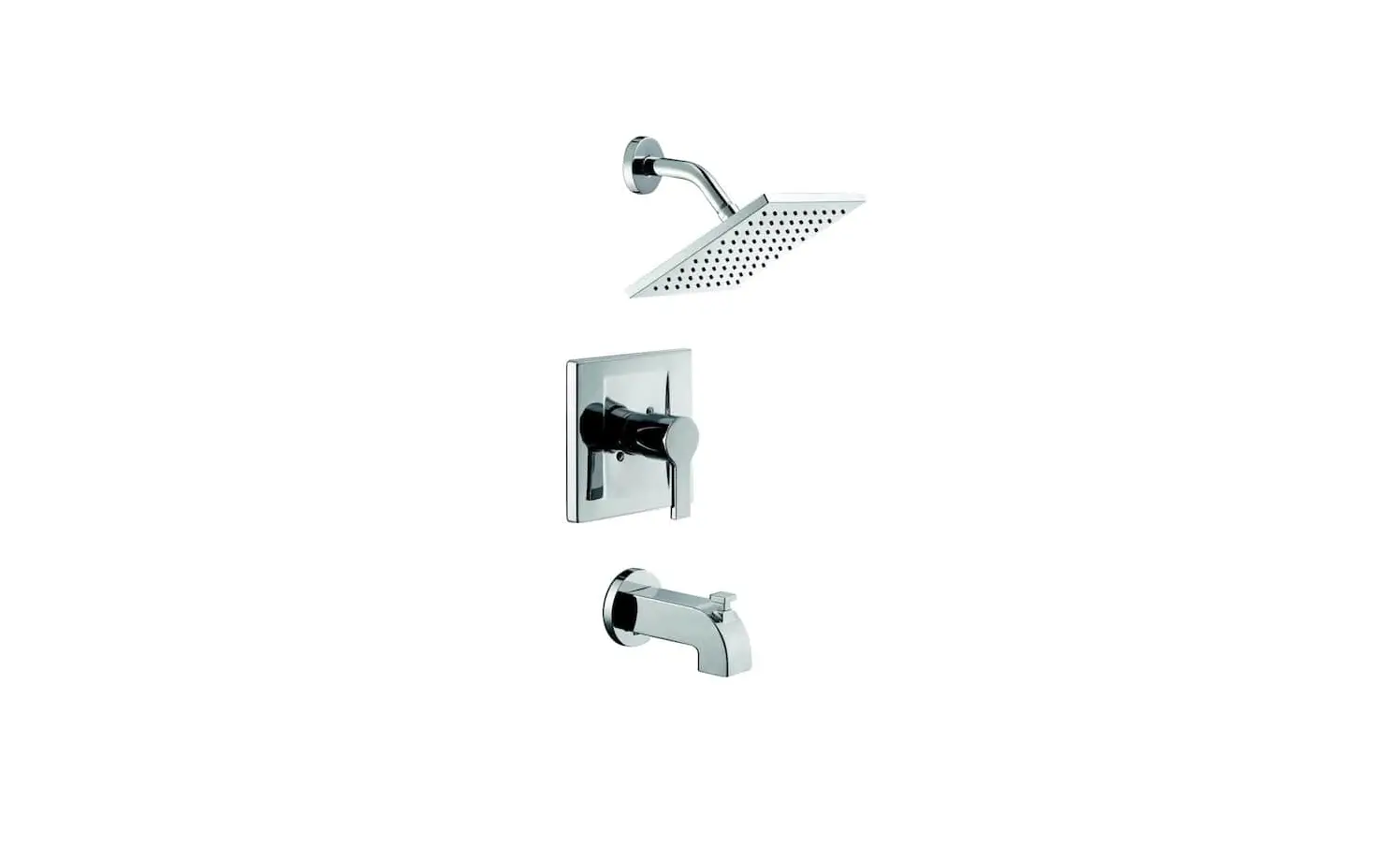
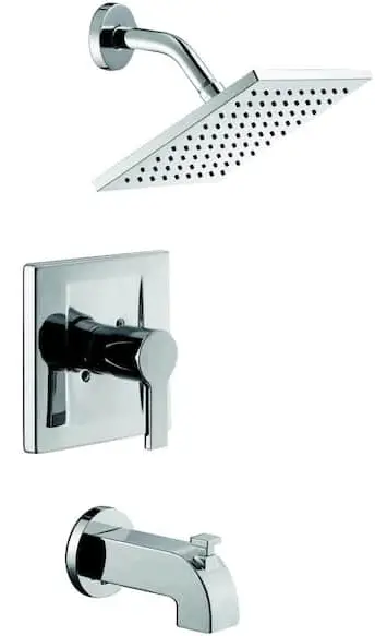
Glacier bay 873W-6101 SINGLE-HANDLE TUB AND SHOWER FAUCET
THANK YOU
We appreciate the trust and confidence you have placed in Glacier Bay through the purchase of this tub and shower faucet. We strive to continually create quality products designed to enhance your home. Visit us online to see our full line of products available for your home improvement needs. Thank you for choosing Glacier Bay!
Important Information
- Do not install this product until you read and understand the instructions in this manual. If you are installing this product for someone else, leave this manual for the owner’s/ user’s reference.
- Inlet ports are designed to allow for 1/2 in. COPPER tubing solder connection or 1/2 in. IPS threading coupling connection. For threaded connections, wrap sealant tape around threaded ends before connecting. If soldering connections, certain inflammable parts should be removed prior to the soldering in order to avoid heat damage. If you are unsure how to properly remove these parts, please call us at 1-855-HD-Glacier.
- Protect your eyes with safety glasses when cutting or soldering water supply lines.
- NOISE AND WATER HAMMER IN PEX SYSTEMS: Due to the inherent exibility of PEX compared with metallic plumbing materials, water hammer and noise can sometimes occur from the pressure surges. It is important to ensure the tubing is not in contact with wallboard, forced air ducts or other high-resonance materials. Clamping or strapping can help prevent these noises. DO NOT USE PEX tubing from the valve to the tub spout.
Pre-Installation
Before beginning the installation of this product, ensure all parts are present. Compare parts with the Package Contents list. If any part is missing or damaged, do not attempt to install the product. Contact customer service for replacement parts.All installations can vary depending on how your previous faucet was installed. Not all supplies for faucet installation are included; however, they are available wherever plumbing supplies are sold. When choosing your installation supplies, make sure they are UPC and/or CSA-approved products.
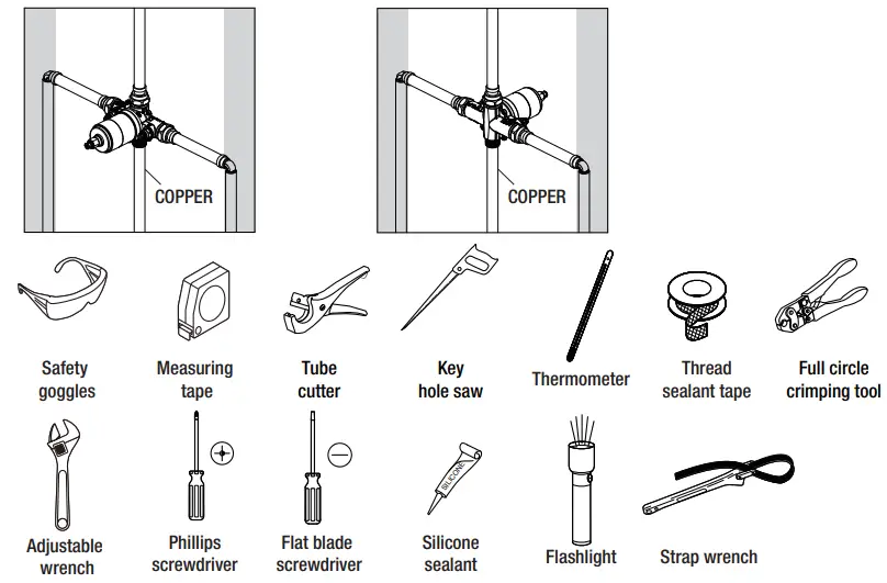
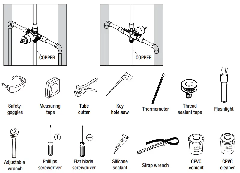
TOOLS AND HARDWARE REQUIRED
If you are replacing your plumbing valve, please review the four common plumbing methods illustrated below: COPPER, IPS, PEX and CPVC. Remove the existing handle and valve trim before replacing your valve. Please follow all local building and plumbing codes.
COPPER (Before soldering, remove the cartridge from the valve)
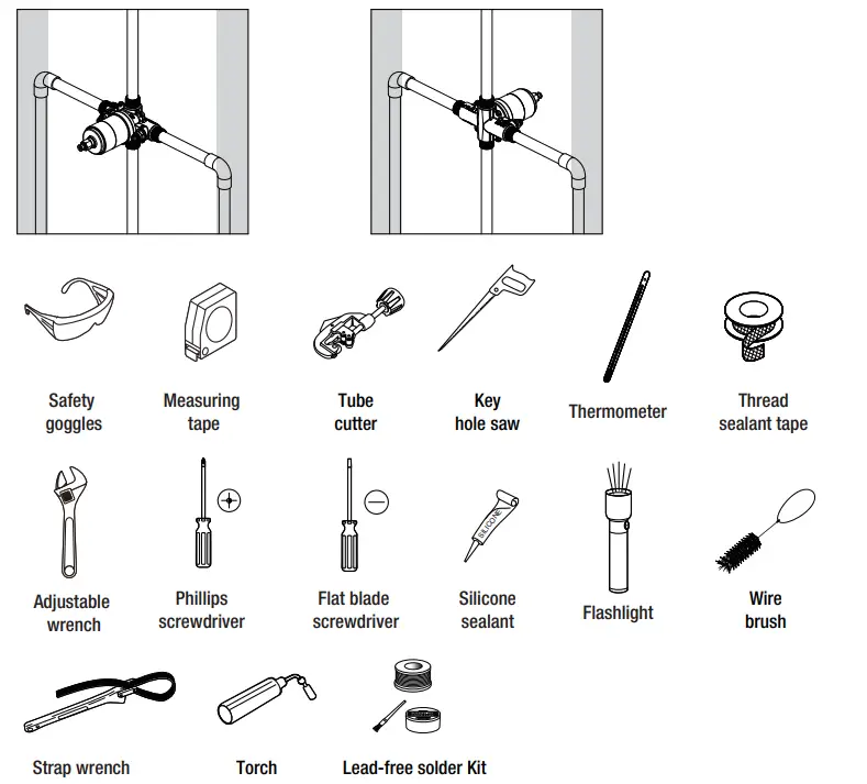
IPS
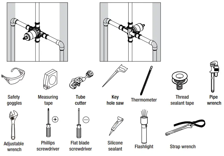
PEX+COPPER
CPVC+COPPER
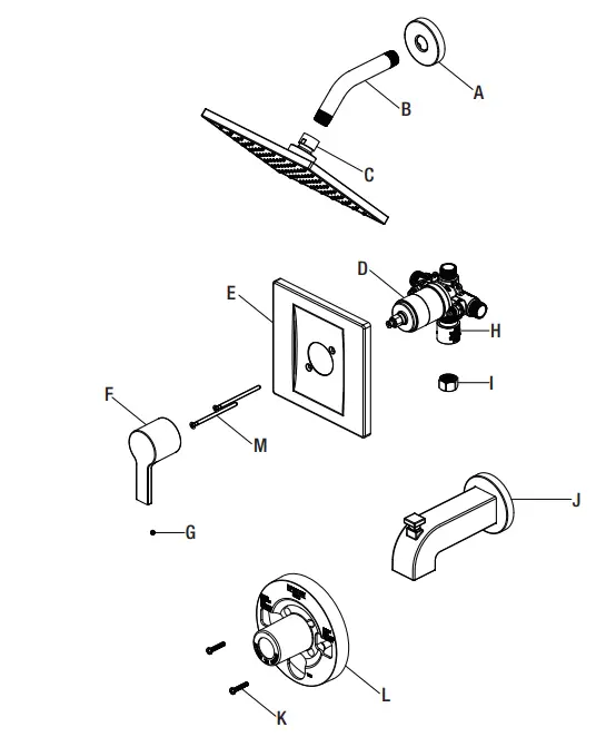
PACKAGE CONTENTS
| Part | Description | Quantity |
| A | Shower lange | 1 |
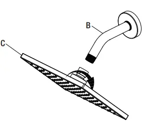
| B | Shower arm | 1 |
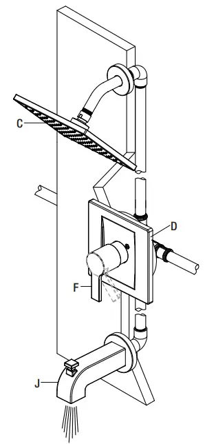
| C | Shower head | 1 |
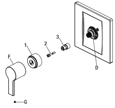
| D | Valve body | 1 |
| E | Escutcheon | 1 |
| F | Handle | 1 |
| G | Set screw | 1 |
| H | Protective cap | 1 |
| I | Plug | 1 |
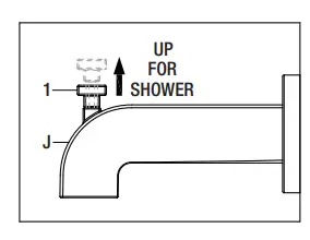
| J | Tub spout | 1 |
| K | Screw | 2 |
| L | Plaster guard | 1 |
| M | Escutcheon screw | 2 |
Installation
Preparing for installation
CAUTION: Always turn off the water supply before removing an existing faucet or replacing any part of a faucet. Open the faucet handle to relieve water pressure and ensure that the water is completely shut off.
- Shut off the water supply to the tub and shower.
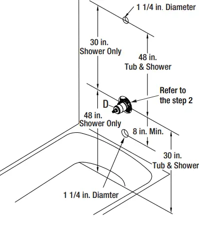
- Verify that the hole sizes and positions of the holes in the wall are correct:
- The shower and tub spout outlet holes should be 1-1/4 in. diameter.
- The valve access hole should refer to step 2.
- The recommended valve depth to the finished wall is 2 in. min. to 2-1/2 in. max.
- Ensure that the valve body (D) cover is flush with the finished exterior surface of the wall. Position the valve body (D) correctly in the wall with the “UP” pointing up. The 8 in. minimum from the valve body to the tub spout is required for proper operation.

Installing the valve body and removing the plaster guard
- a Thin Wall Installation
“Thin Wall” is usually built up with materials such as berglass tub surround and will be the main source of support for the valve. The plaster guard (L) remains attached to the valve. - b Thick Wall Installation
“Thick Walls” are usually built up with materials such as cement board, drywall, tile, etc. The plaster guard (L) is positioned so that it is flush with the finished wall. This ensures that the valve will be at the correct position to accept the trim. The depth for valve body (D) in wall is measured from the center of the shower outlet to the finished wall surface. The accepted depth distance is 1-1/2 in. to 2-1/2 in.. When the depth distance is 1-1/2 in. to 2 in., there will be interference between the plaster guard and escutcheon, suggest removing the plaster guard after the wall installation - Unscrew the screws (K), and remove the plaster guard (L).
NOTE: Be sure to position the body (D) correctly in the wall, with the markings “UP” facing upward.
Installing the supply connections
NOTE: The hot water supply lines go into the H inlet, and the cold water supply lines go into the C inlet. Do not use PEX or CPVC between the valve and spout.
- Wrap thread sealant tape (not included) around the pipe threads in a clockwise direction, as shown.
- Connect the hot and cold water supply lines (1, not included), the shower outlet pipe (2, not included), and tub outlet pipe (3, not included) by threading them into the valve body (D) in a clockwise direction.
- Tighten the pipes to the valve body (D) with a pipe wrench (not included).
- Connect the pipe elbows (4, not included) to the end of the shower outlet and tub outlet pipes.
NOTE: If you do not wish to install the tub outlet, insert the plug (I) into the bottom of the valve body (D).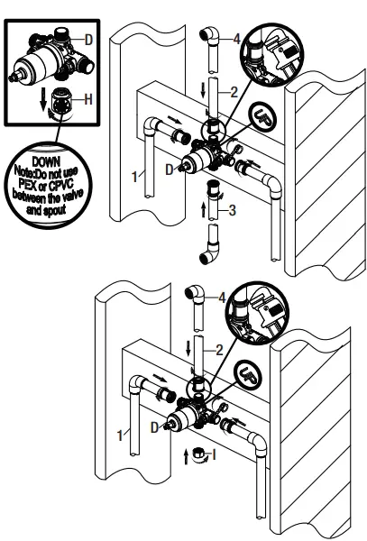
Back to back installation
f the hot and cold inlets are reversed (hot on right and cold on left), remove the screw, inverter, sleeve, and bonnet from the valve body (D) with reversed supply connections. Rotate cartridge 180°, so H appear on the right. Install the cartridge making sure that the key is fully engaged with the slot in the valve body (D). Slide the bonnet over the cartridge and thread it onto the body. Hand tighten securely. Reassemble sleeve, inverter and screw.If you are not making a reverse or back-to-back installation, skip the step, and continue with step 5.
NOTE: Never install the valve body (D) upside down!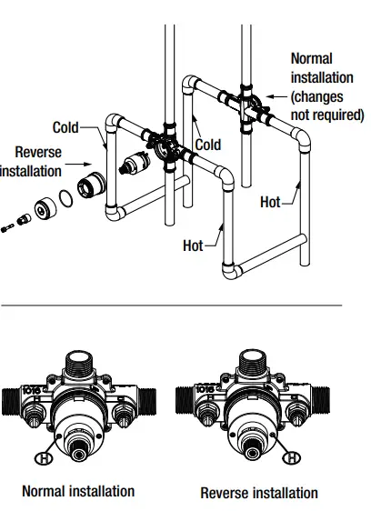
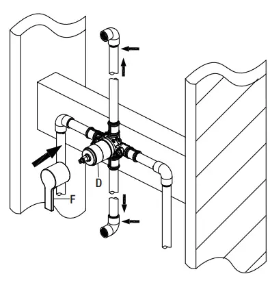
Flushing the water outlets and checking for leaks
- Place the handle (F) on the valve body (D)
inverter and turn the handle (F) to the full on mixed position. Turn on the hot and cold water supply lines and allow the water to flow from the outlets for one minute, or until all foreign matter has been flushed out. Check for leaks. - Shut off the water at the faucet and supply lines. Remove the handle (F).

Installing the plaster guard
- Place the plaster guard (L) onto the body (D) and secure with the screws (K).
NOTE: Be sure to position the plaster guard (L) correctly onto the body (D), with the markings “SHOWER” facing upward.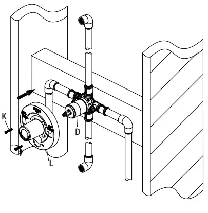
Installing the shower arm
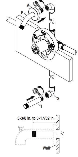
- Insert the long end of the shower arm (B) through the flange (A), and wrap thread sealant tape (not included) around the long end of the shower arm (B) in a clockwise direction, as shown. Install the long end of the shower arm (B) into the pipe elbow inside the wall. Carefully tighten the shower arm (B) with a clean strap wrench. Do not over-tighten.
- Wrap thread sealant tape around the pipe threads of the tub spout outlet (1, not included) in a clockwise direction, as shown.
- Connect the tub spout outlet pipe (the tub spout outlet pipe should project 3-3/8 in. to 3-17/32 in. from the finished wall) to the lower pipe elbow (2, not included). Tighten the elbow and tub spout outlet pipe connections with a strap wrench.

Installing the tub spout
- Wrap thread sealant tape around the pipe threads of the tub spout (J) outlet in a clockwise direction, as shown.
- Thread the spout (J) onto the threaded connection in a clockwise direction until the spout (J) becomes flush with the finished wall.
- Use the strap wrench to tighten the spout (J).
NOTE: Apply silicone to the side of the spout flange (1). Clean away any excess putty.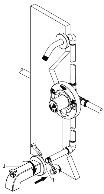
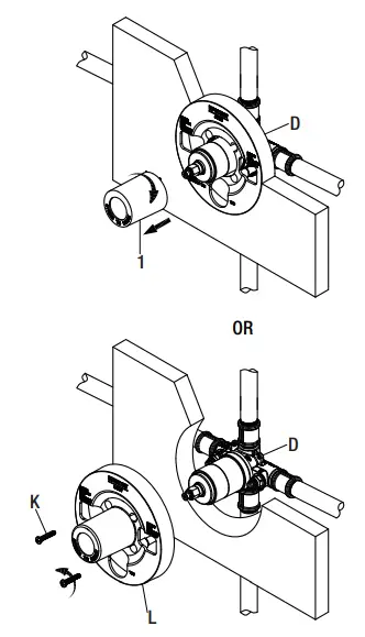
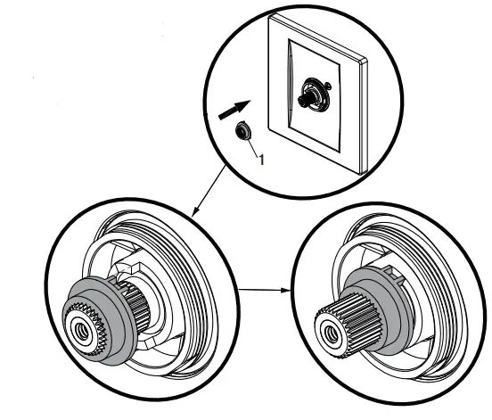
Removing the plastic cap
- Before installing the escutcheon (E), remove the plastic cap (1) from the valve body (D) by twisting the cap in a clockwise direction when the depth distance which is measured from center of shower outlet to finished wall surface is 2 in. to 2-1/2 in.. Or unscrew the screws (K) and remove the plaster guard (L) when the depth distance which is measured from center of shower outlet to finished wall surface is 1-1/2 in. to 2 in.

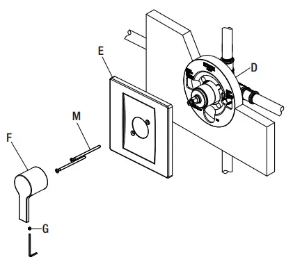
Installing the escutcheon and handle
- Install the escutcheon (E) onto the valve body (D) using the escutcheon screws (M).
- Place the handle (F) onto the valve body (D) and tighten the set screw (G) with the Hex wrench (Hex: 2.5 mm) provided.

Installing the shower head
- Attach the shower head (C) to the shower arm (B). Carefully tighten the shower head (C) with a clean strap wrench.

Checking for leaks
- Turn the handle to the full on mixed position. When the valve is turned on, water normally flows through the tub spout (J). To activate the shower, turn the valve on and pull the knob (1) up. Hold the knob (1) until the water flows continiously from the shower head (C). Check for leaks.
- Shut off the water at the faucet and supply lines.


Adjusting the Temperature
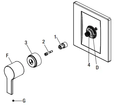
Removing the handle, sleeve and inverter
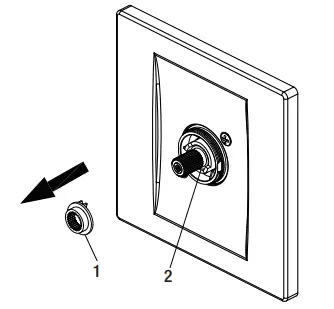
- Unscrew the set screw (G) from the handle (F), and then remove the handle (F) from the valve body (D).
- Unscrew the sleeve (1) from the valve body (D).
- Unscrew the screw (2) from the inverter (3), and then remove the inverter (3) from the valve body (D).

Removing the red limit stop ring
- Remove the red limit stop ring (1) from the cartridge assembly (2).

Adjusting the desired maximum water temperature
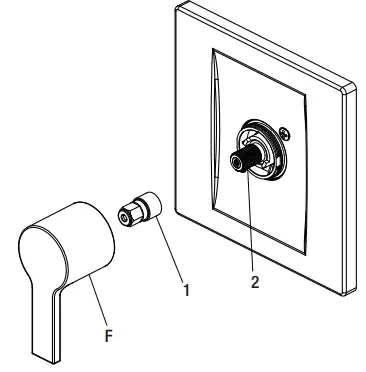
- Place handle (F) and inverter (1) onto the cartridge stem.
- Slowly turn the valve stem (2) counterclockwise to adjust the desired maximum water temperature.

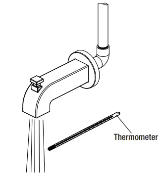
Rechecking the temperature
- A water temperature for a comfortable bath or shower is typically between 90°F-100°F. Rotate stem clockwise to turn off.

Reinstalling the red limit stop ring
- Reinstall the red limit stop ring (1) and readjust the teeth engagement position so that the stem cannot move beyond the adjusted point.

Reinstalling the inverter, sleeve and handle
NOTE: Rotate the cartridge stem (4) clockwise to turn off the water before you install the handle.
- Place the inverter (1) onto the valve body (D) and rotate the inverter (1) with notch facing down and reinstall the stem adapter and screw. Then secure with the screw (2).
- Screw the sleeve (3) onto the valve body (D).
- Place the handle (F) onto the valve body (D) and secure with the set screw (G).

Care and Cleaning
- To clean, wipe down with a damp cloth and towel dry.
- Do not use abrasive cleaners, steel wool, or harsh chemicals when cleaning this faucet, or the warranty will be voided.
Troubleshooting
NOTE: Refer to the service parts section in this manual for a detailed drawing showing the location of the parts listed below.
| Problem | Possible Cause | Solution |
| Hot and cold are reversed. | Lines reversed or cartridge installed upside down. | □ Rotate the cartridge stem 180° so that the notch is facing down towards the drain. |
| There is no or a low water low. | One or both water supplies are not turned on. | □ Turn both water supply valves counterclockwise to the on position. |
| There is leaking or dripping from the spout when the handle is closed. | Grommets not sealing properly. | □ Replace the cartridge. |
| Water comes out of tub spout and showerhead at the same time. | If the water lowing pattern switch to shower from tub spout, the leak from tub spout at less than 0.01 GPM, that it is a normal phenomenon. Or consider the cause below. | □ Change the pipe to IPS or COPPER. □ The distance from the showerhead and valve moved to at least 48 in.. |
| The pipe used between the valve and tub spout is not the 1/2 in. IPS nor COPPER pipe is incorrect. | □ Remove the tub spout and lush out debris and/or replace the undersized line or fittings. | |
| The distance between the valve and the showerhead is less than 48 in.. | □ Remove the valve and reinstall it using the correct orientation. | |
| There is a restriction between the valve and the tub spout. | ||
| The valve is installed upside down. | ||
| The temperature range is restricted. | Temperature limit stop is out of position. | □ Refer to the module “Adjusting the Temperature”. |
| Unable to install the handle or the handle rubs against the escutcheon. | The valve is installed too far back from the finished wall. | □ Reinstall the valve refer to the step 2. |
| The handle is hard to turn. | The bonnet nut is overtighten. | □ Loosen the bonnet nut and reinstall, do not overtighten. |
Service Parts
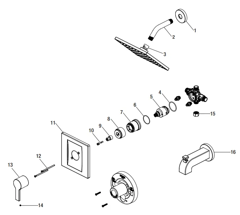
| Part | Description | Part Number |
| 1 | Shower lange | RP38049* |
| 2 | Shower arm | RP38019* |
| 3 | Shower head | RP38245* |
| 4 | O-ring | RP60101 |
| 5 | Cartridge | RP20006 |
| 6 | O-ring | RP60091 |
| 7 | Bonnet nut | RP70437 |
| 8 | Sleeve | RP80297* |
| Part | Description | Part Number |
| 9 | Inverter | RP64043 |
| 10 | Screw | RP50020 |
| 11 | Escutcheon | RP80469* |
| 12 | Escutcheon screw | RP50066* |
| 13 | Handle | RP13398* |
| 14 | Set screw | RP50002 |
| 15 | Plug | RP70365 |
| 16 | Spout | RP33068* |
Specify Finish
Many replacement cartridges, aerators, and drain assemblies can be purchased at your local Home Depot store or online at HOMEDEPOT.COM
Warranty
LIMITED LIFETIME WARRANTY
Glacier Bay products are manufactured with superior quality standards and workmanship and are backed by our limited lifetime warranty. Glacier Bay products are warranted to the original consumer purchaser to be free of defects in materials or workmanship. We will replace FREE OF CHARGE any product or parts that prove defective. Simply, return the product/part to any of The Home Depot retail locations or call 1-855-HD-GLACIER (1-855-434- 5224) to receive the replacement item. Proof of purchase (original sales receipt) from the original consumer purchaser must be made available for all Glacier Bay warranty claims. This warranty excludes incidental/inconsequential damages and failures due to misuse, abuse or normal wear and tear. This warranty excludes all industrial, commercial & business usage, whose purchasers are hereby, extended the duration of the warranty. Some states and provinces do not allow the exclusion or limitation of incidental or consequential damages, so the above limitations may not apply to you. This warranty gives you specific legal rights and you may also have other rights that vary from state to state and province to province. Please see a store or contact 1-855-HD-GLACIER for more details.
Questions, problems, missing parts?
Before returning to the store, call Glacier Bay Customer Service
8 a.m. – 7 p.m., EST, Monday – Friday
9 a.m. – 6 p.m., EST, Saturday
1-855-HD-GLACIER (1-855-434-5224)
HOMEDEPOT.COM/GLACIERBAY Retain this manual for future use.


