![]() ONE-HANDLE WALLMOUNT TUB FILLER
ONE-HANDLE WALLMOUNT TUB FILLER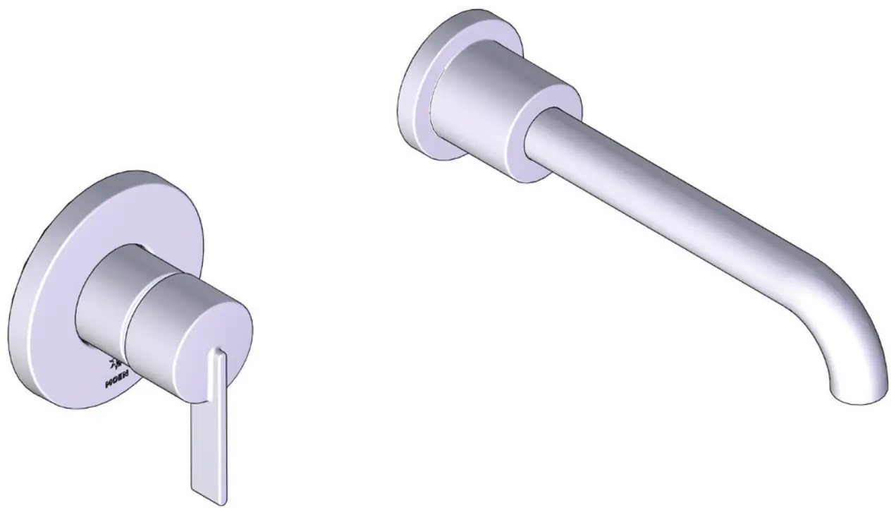
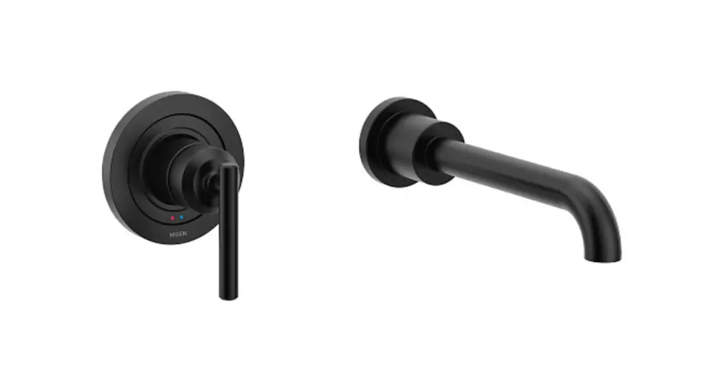
WT961BL One-Handle Wallmount Tub Filler
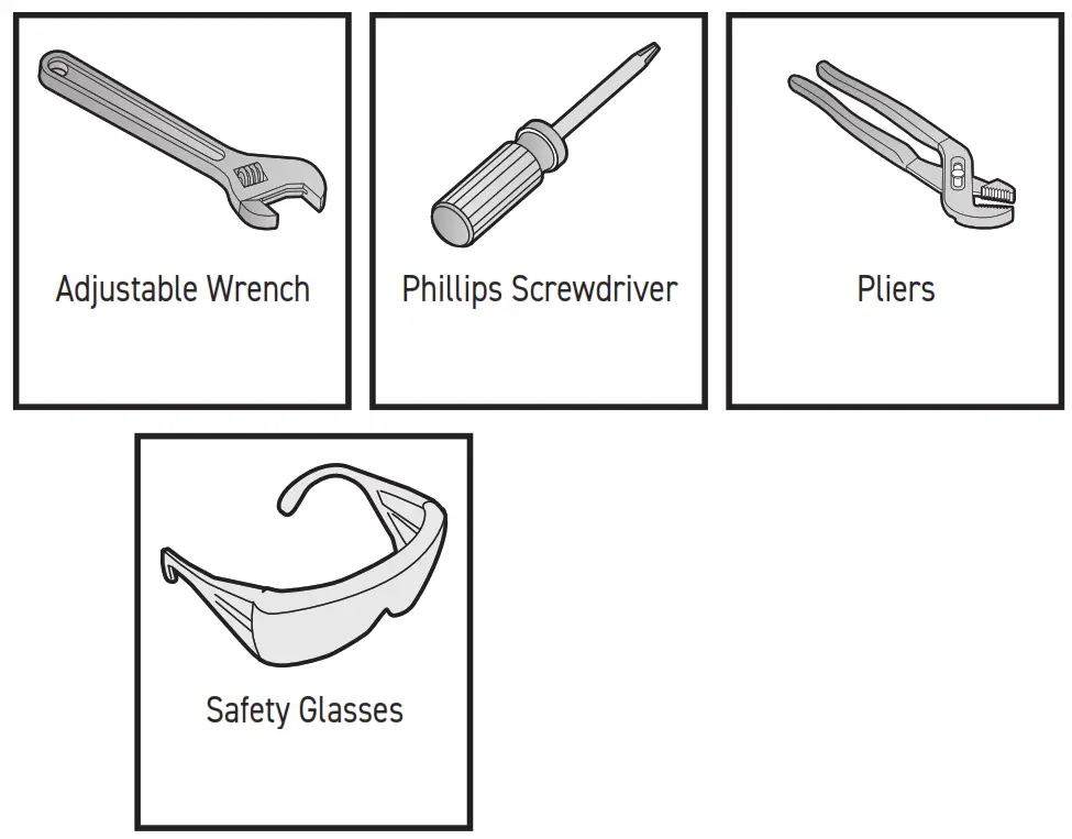
HELPFUL TOOLS
For safety and ease of faucet replacement, Moen recommends the use of these helpful tools.
Required for Optional Hardwire Installation
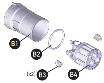
| Exploded View of Part B | Some models |
 |  |
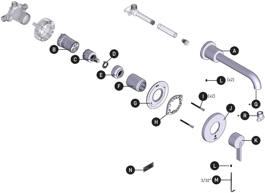
Parts List
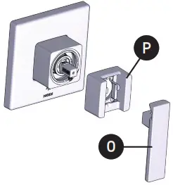
| A. Tub Spout B. Installation sleeve with pressure balance puck and adapter B1. Install sleeve B2. O-Ring B3. Inlet Seal (x2) B4. Pressure balance puck C. Cartridge D. Adjustable Temperature Limit Stop E. Cartridge Nut F. Sleeve G. Mounting Plate H. Snap Ring I. Screws (x2) J. Escutcheon | K. Handle L. Set Screw (x2) M. Hex Wrench (3/32”) N. Grease Pack O. Handle * P. Hub Assembly * Q. Stream Straightener * (comes pre-installed) R. Aerator Tool * *Certain models |
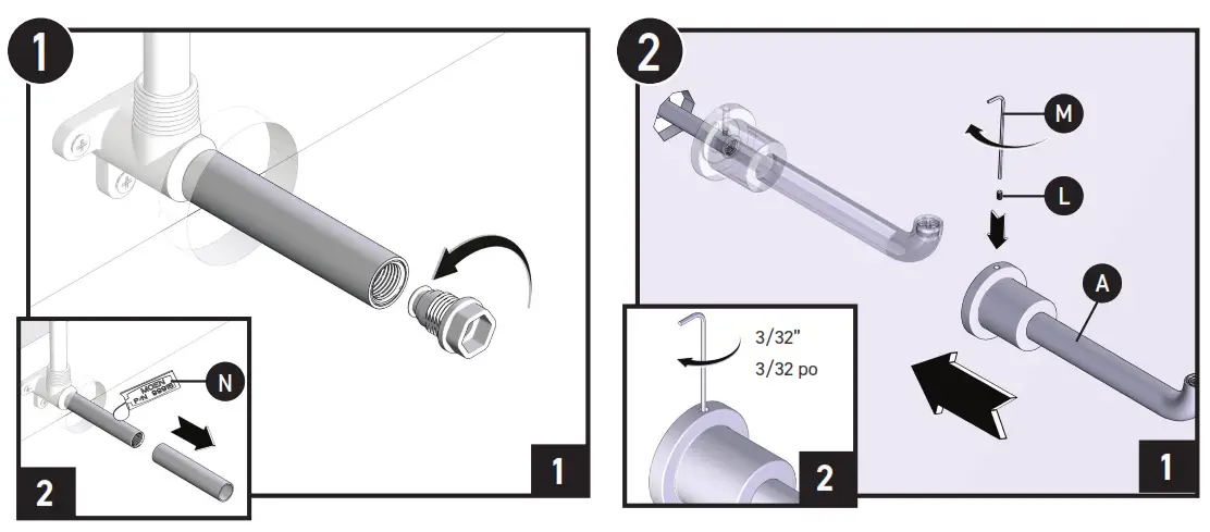 | |
| 1. Remove flush plug. 2. Remove the protective sleeve, and apply grease (N). | 1. Install tub spout (A) upside down onto the pipe. 2. Barely tighten tub spout set (L) screw with 3/32” hex wrench (M). |
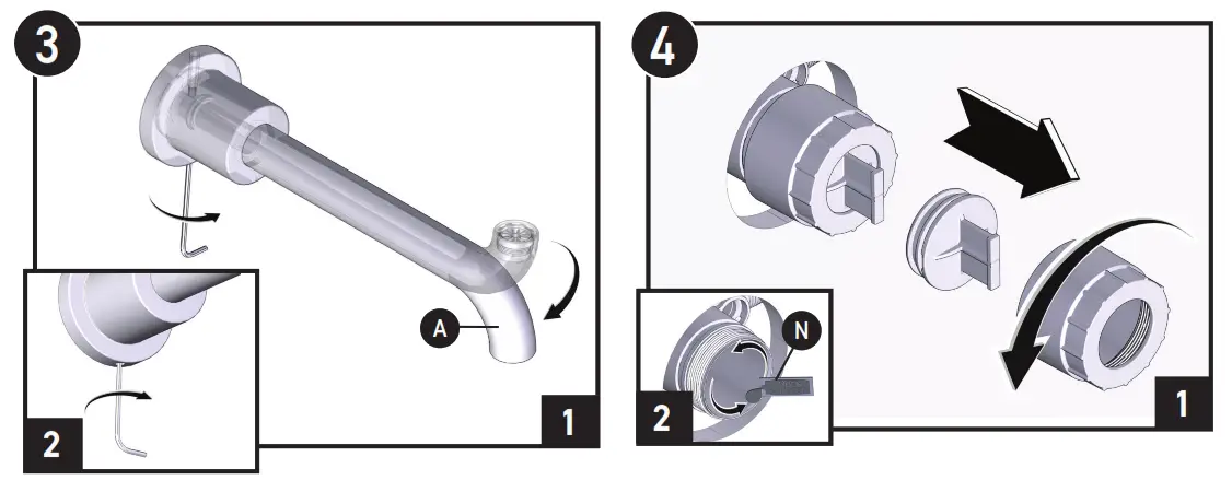 | |
| 1. Rotate tub spout (A) to the proper position, with the spout opening facing down. 2. Secure spout by tightening tub spout set screw. | 1. Remove flush plug before applying grease. 2. Apply grease to the outer ring and inside of the valve bore using a grease pack (N). |
INS11937 – 07/21
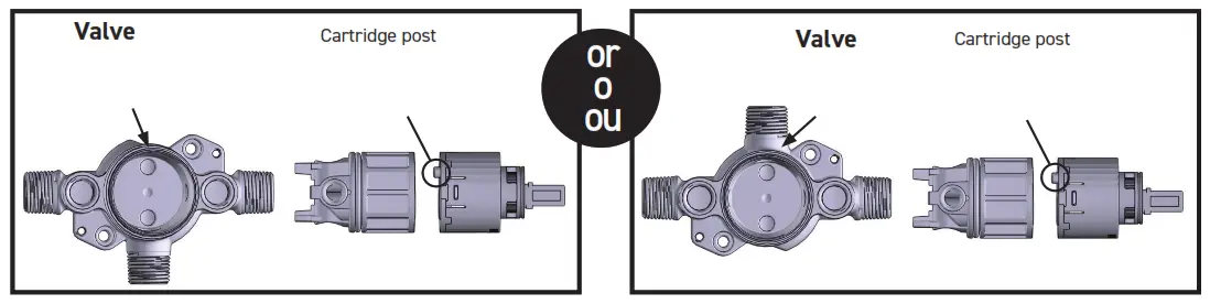
Note: 1215 Cartridge posts should always face up regardless of valve orientation.
Caution: 1215 Cartridge is NON-Pressure Balancing, and not for use in showering applications.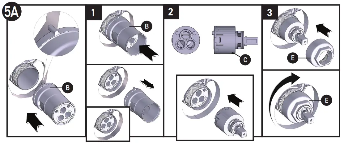
- Align the tab on the Installation sleeve (B) facing up and place it in line with the valve. Push Adapter (B2) and puck (B6) out of the installation sleeve (B1) into the valve until they bottom.
- Align 2 posts on cartridge (C) to the mating feature in the adapter and push the cartridge into the valve until it stops.
- Tighten cartridge nut (E) onto valve by turning it clockwise until hand tight, and then turn an additional ¼ turn with a wrench. Note: proper torque of nut to the valve housing is 106-115 in-lbs (12-13Nm).
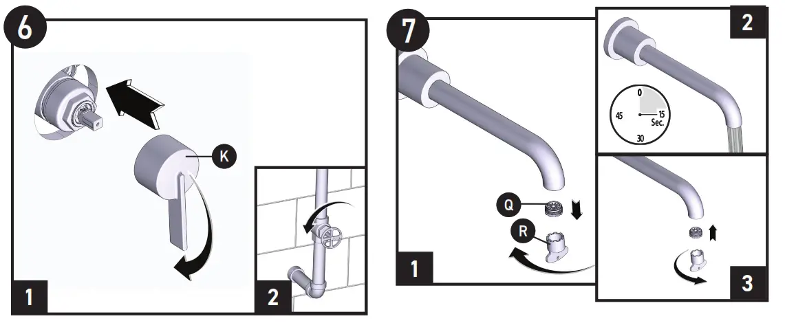 | |
| 1. Use handle (K) to verify the cartridge is closed. (Push handles down to close.) 2. Turn on the hot and cold water supply and check for leaks. | 1. Remove stream straightener (Q) with a tool (R) for flushing. 2. Turn on hot and cold water and flush any debris for 15 seconds. Turn off the hot and cold water 3. Re-insert the stream straightener into the spout and tighten with the aerator tool. |
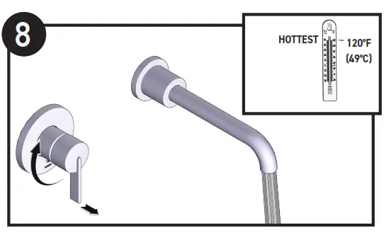
Open a handle to full hot to test the hot water temperature. Close handle if desired water temperature has been met. Hot water temperature should not exceed 120°F.
TO REDUCE MAXIMUM TEMPERATURE GO TO THE STEP
9.1 IF NOT, GO TO STEP 11
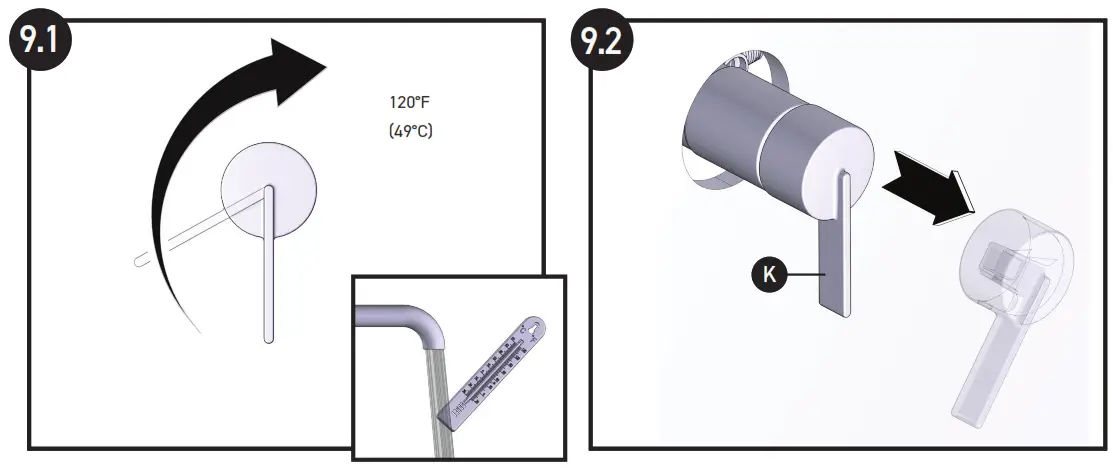 | |
| Rotate the lever until the water is to the maximum desired temperature, not to exceed 120 o F (49oC). Seasonal maintenance of the maximum outlet temperature may be required due to changes in groundwater temperature. | Close and Remove the handle (K). |
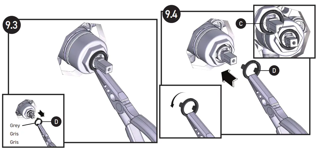 | |
| Remove the adjustable temperature limit stop (D). | Install the adjustable temperature limit stop (D) so it is in contact with the bottom of the stop on the left side of the cartridge (C), as shown in the inset. |
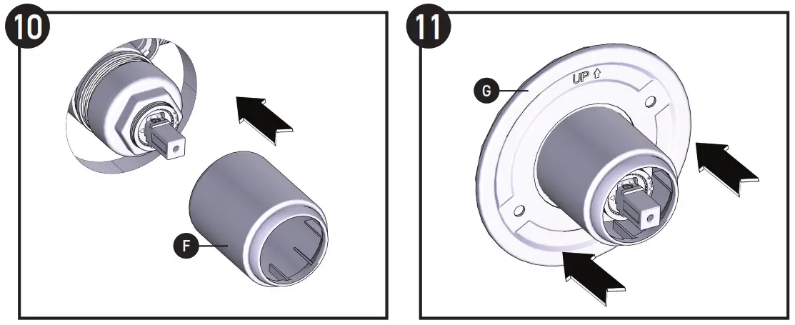 | |
| Slide sleeve (F) onto valve until it stops and orient markings downward. | Push mounting plate (G) onto sleeve until it bottoms on the wall and align holes to threaded holes in the valve. |
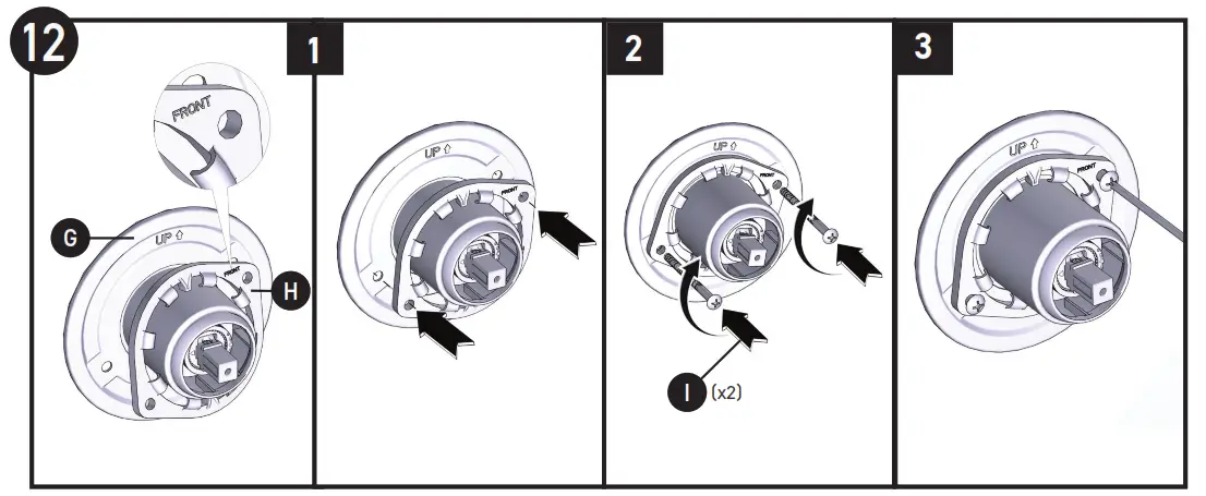
 Orient the snap ring (H) to mounting plate (G) as shown with “FRONT” text facing forward and upright.
- Insert screws (I) (X2) through the snap ring (H) and mounting plate (G) and secure to the valve until the mounting plate bottoms on the finished wall. Do not over-tighten.
- Ensure the snap ring is centered on the sleeve for proper escutcheon placement, if off-center, loosen screws, reposition, and secure.
 Orient the snap ring (H) to mounting plate (G) as shown with “FRONT” text facing forward and upright.
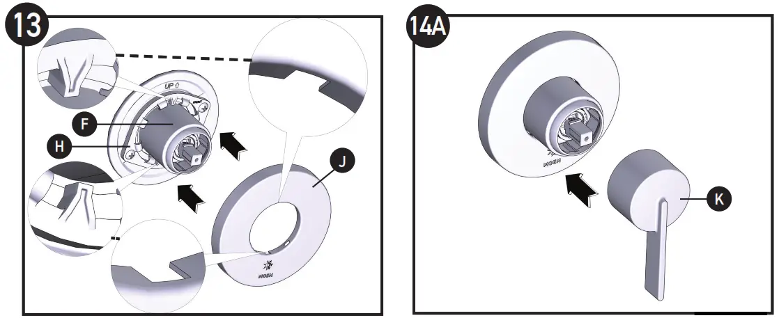 | |
| 1. Orient slots in the backside of the escutcheon (J) with tabs on the top and bottom of the snap ring (H). 2. Snap escutcheon (J) onto the snap ring (H). 3. Ensure escutcheon (J) is centered on the sleeve (F) and markings are level. | Place the handle (K) onto the cartridge stem. |
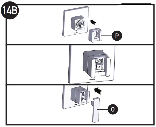
For multi-piece handle designs
- bully snap handle hub assembly (P) into the sleeve
- Position hub as shown with adapter parallel to cartridge stem
- Place handle (O) onto cartridge stem.
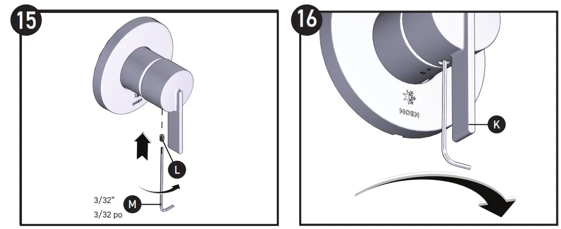 | |
| Insert 3/32” hex wrench (M) into set screw (L). | Tighten the set screw into the handle (K). |
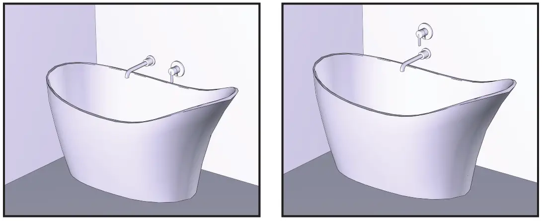 Installation complete.
Moen Limited Lifetime Warranty
Moen products have been manufactured under the highest standards of quality and workmanship. Moen warrants to the original consumer purchaser for as long as the original consumer purchaser owns their home (the “Warranty Period” for homeowners), that this product will be leak- and drip-free during normal use, and all parts and finishes of this product will be free from defects in material and manufacturing workmanship. All other purchasers (including purchasers for industrial, commercial, and business use) are warranted for a period of 5 years from the original date of purchase (the “Warranty Period” for non-homeowners).
If this product should ever develop a leak or drip during the Warranty Period, Moen will FREE OF CHARGE provide the parts necessary to put the product back in good working condition and will replace FREE OF CHARGE any part or finish that proves defective in material and manufacturing workmanship, under normal installation, use, and service. Replacement parts may be obtained by calling 1-800-2896636 (Canada 1-800-465-6130), or by writing to the address shown. Proof of purchase (original sales receipt) from the original consumer purchaser must accompany all warranty claims. Defects or damage caused by the use of other than genuine Moen parts is not covered by this warranty. This warranty is applicable only to products purchased after December, 1995 and shall be effective from the date of purchase as shown on the purchaser’s receipt.
This warranty is extensive in that it covers the replacement of all defective parts and finishes. However, damage due to installation error, product abuse, product misuse, or use of cleaners containing abrasives, alcohol, or other organic solvents, whether performed by a contractor, service company, or yourself, are excluded from this warranty. Moen will not be responsible for labor charges and/or damage incurred in installation, repair, or replacement, nor any indirect, incidental, or consequential damages, losses, injury, or costs of any nature relating to this product. Except as provided by law, this warranty is in lieu of and excludes all other warranties, conditions, and guarantees, whether expressed or implied, statutory or otherwise, including without restriction those of merchantability or of fitness for use.
Some states, provinces, and nations do not allow the exclusion or limitation of incidental or consequential damages, so the above limitations or exclusions may not apply to you. This warranty gives you specific legal rights and you may also have other rights which vary from state to state province to province, and nation to nation. Moen will advise you of the procedure to follow in making warranty claims. Simply write to Moen Incorporated using the address below. Explain the defect and include proof of purchase and your name, address, area code, and telephone number.![]()
| Moen Incorporated 25300 Al Moen Drive North Olmsted, Ohio 44070-8022 The U.S.A. | Moen de Mexico, S.A. de C.V. Carretera Saltillo-Monterrey KM 14.7 Ramos Arizpe, Coahuila Mexico 25900 | Moen Inc. 2816 Bristol Circle Oakville, Ontario L6H 5S7 Canada |

PLEASE CONTACT MOEN FIRST
For Installation Help, Missing or Replacement Parts
(USA) 1-800-BUY-MOEN (1-800-289-6636) www.moen.com
(Canada) 1-800-465-6130 www.moen.ca
The image is for reference only
(Style varies by model)
Record Purchased Model Number:
Register Online:
www.moen.com/product-registration
INS11937 – 07/21
©2021 Moen Incorporated


