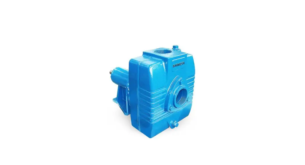
![]() BSP15ICU Self-Priming Frame Mounted Pump
BSP15ICU Self-Priming Frame Mounted Pump
Instruction Manual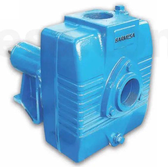
![]() IMPORTANT! – Read all instructions in this manual before operating or servicing a pump.
IMPORTANT! – Read all instructions in this manual before operating or servicing a pump.
Before installation, read the following instructions carefully. Failure to follow instructions and safety information could cause serious bodily injury, death, and/or property damage. Each Barmesa product is carefully inspected to insure proper performance. Closely following these instructions will eliminate potential operating problems, assuring years of trouble-free service.
![]() “Danger” indicates an imminently hazardous situation that, if not avoided, WILL result in death or serious injury.
“Danger” indicates an imminently hazardous situation that, if not avoided, WILL result in death or serious injury.![]() “Warning” indicates an imminently hazardous situation that, if not avoided, MAY result in death or serious injury.
“Warning” indicates an imminently hazardous situation that, if not avoided, MAY result in death or serious injury.
![]() CAUTION “Caution” indicates a potentially hazardous situation that, if not avoided, MAY result in minor or moderate injury.
CAUTION “Caution” indicates a potentially hazardous situation that, if not avoided, MAY result in minor or moderate injury.![]() IMPORTANT! – Barmesa Pumps is not responsible for losses, injury, or death resulting from failure to observe these safety precautions, misuse, abuse, or misapplication of pumps or equipment.
IMPORTANT! – Barmesa Pumps is not responsible for losses, injury, or death resulting from failure to observe these safety precautions, misuse, abuse, or misapplication of pumps or equipment.
![]() ALL RETURNED PRODUCTS MUST BE CLEANED, SANITIZED, OR DECONTAMINATED PRIOR TO SHIPMENT, TO INSURE E MPLO YEES WILL NOT BE EXPOSED TO HEALTH HAZARDS IN HANDLING SAID MATERIAL. ALL APPLICABLE LAWS AND REGU LATIONSSH ALL APPLY.
ALL RETURNED PRODUCTS MUST BE CLEANED, SANITIZED, OR DECONTAMINATED PRIOR TO SHIPMENT, TO INSURE E MPLO YEES WILL NOT BE EXPOSED TO HEALTH HAZARDS IN HANDLING SAID MATERIAL. ALL APPLICABLE LAWS AND REGU LATIONSSH ALL APPLY.
![]() WARNING Installation, wiring, and junction connections must be in accordance with the National Electric Code and all applicable state and local codes. Requirements may vary depending on usage and location.
WARNING Installation, wiring, and junction connections must be in accordance with the National Electric Code and all applicable state and local codes. Requirements may vary depending on usage and location.
WARNING
Installation and servicing is to be conducted by qualified personnel only.![]() Keep clear of suction and discharge openings. Do not insert fingers in the pump with power connected; the rotating cutter and/or impeller can cause serious injury.
Keep clear of suction and discharge openings. Do not insert fingers in the pump with power connected; the rotating cutter and/or impeller can cause serious injury.
![]() Always wear eye protection when working on pumps. Do not wear loose clothing that may become entangled in moving parts.
Always wear eye protection when working on pumps. Do not wear loose clothing that may become entangled in moving parts.
![]() Pumps build up heat and pressure during operation. Allow time for pumps to cool before handling or servicing the pump or any accessory items associated with or near the pump.
Pumps build up heat and pressure during operation. Allow time for pumps to cool before handling or servicing the pump or any accessory items associated with or near the pump.![]() Risk of electric shock. To reduce the risk of electric shock, always disconnect the pump from the power source before handling any aspect of the pumping system. Lock out power and tag.
Risk of electric shock. To reduce the risk of electric shock, always disconnect the pump from the power source before handling any aspect of the pumping system. Lock out power and tag.
Do not use these pumps in water over 160° F. Do not exceed the manufacturer’s recommended maximum performance, as this could cause the motor to overheat.
![]() This pump is not intended for use in swimming pools or water installations where there is human contact with the pumped fluid.
This pump is not intended for use in swimming pools or water installations where there is human contact with the pumped fluid.
![]() Operation against a closed discharge valve will cause premature bearing and seal failure on any pump, and on end, suction and self-priming pump the heat build may cause the generation of steam with resulting dangerous pressures. It is recommended that a high case temperature switch or pressure relief valve be installed on the pump body.
Operation against a closed discharge valve will cause premature bearing and seal failure on any pump, and on end, suction and self-priming pump the heat build may cause the generation of steam with resulting dangerous pressures. It is recommended that a high case temperature switch or pressure relief valve be installed on the pump body.
![]() Carefully read instruction manuals supplied with motor or engine before operating or servicing.
Carefully read instruction manuals supplied with motor or engine before operating or servicing.
![]() Make sure lifting handles are securely fastened each time before lifting. Do not operate the pump without safety devices in place. Always replace safety devices that have been removed during service or repair. Secure the pump in its operating position so it can not tip over, fall or slide.
Make sure lifting handles are securely fastened each time before lifting. Do not operate the pump without safety devices in place. Always replace safety devices that have been removed during service or repair. Secure the pump in its operating position so it can not tip over, fall or slide.
![]() These pumps are not to be installed in locations classified as hazardous in accordance with the National Electric Code, ANSI/NFPA 70.
These pumps are not to be installed in locations classified as hazardous in accordance with the National Electric Code, ANSI/NFPA 70.
IMPORTANT! – Prior to installation, record Model Number, Serial, Amps, Voltage, Phase, and HP from the pump nameplate for future reference. Also, record the Voltage and Current Readings at Startup:
Model Number:_____________
Serial: ____________________
Amps:_______ Voltage:_______
Phase:_______ HP:_______
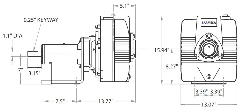
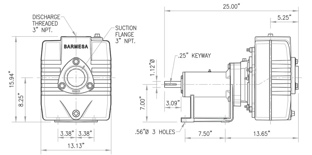
Specifications & Dimensions
| SUCTION/DISCHARGE: | 3″ x 3″ NPT, female flange. |
| LIQUID TEMPERATURE: | 160 °F (71 °C) max. |
| VOLUTE: | Cast iron ASTM A-48 class 30. |
| BODY: | Cast iron ASTM A-48 class 30. |
| PEDESTAL: | Cast iron ASTM A-48 class 30. |
| IMPELLER: | Open, trash type, dynamically balanced. Cast iron ASTM A-48 class 30. |
| SHAFT: | Stainless steel. |
| SHAFT SLEEVE: | Stainless steel. |
| O-RINGS: | Buna-N. |
| PAINT: | Air dry enamel, water-based. |
| SEAL: | Single mechanical with lip seal, water lubricated. Ceramic stationary part, carbon ring seal, and exclusion in the rotating part. Buna-N elastomer and stainless steel spring. |
| CHECK VALVE: | Flap-neoprene, the weight of steel. |
| HARDWARE: | Steel. |
| BEARING-DRIVE END: | Single row, ball, grease lubricated. |
| BEARING-PUMP END: | Single row, ball, grease lubricated. |
| SHIM SET: | Stainless steel. |
| OPTIONAL: | Bronze fitted volute and impeller |
Recommendations, Warnings & Installation
▶Receiving inspection
Upon receiving the pump, it should be inspected for damage or shortages. If damage has occurred, file a claim immediately with the company that delivered the pump. If the manual is removed from the packaging, do not lose or misplace it.
▶Storage
Any product that is stored for a period longer than six (6) months from the date of purchase should be bench tested prior to installation. A bench test consists of, checking the
impeller to assure it is free turning and a run test to assure the motor (and switch if provided) operates properly.
▶Controls
Manual models require a separate approved pump control device or panel for automatic operation. Be sure the electrical specification of the control selected properly matches the electrical specifications of the pump
▶Installation
Location – The pump should be located as near as possible to the liquid to be pumped and in no case should the pump be more than 25 feet above the surface of the liquid supply. The pump should always be as level as possible.
Locate the pump on a firm footing to make sure the pump will not move due to vibration. Flex coupled and Vbelt driven units should be permanently grouted onto a cement foundation. The pumps should be level to provide favorable operating conditions. In addition, the flexible coupling should be realigned after grouting in order to eliminate excessive wear on the coupling.
Allow a minimum of 18 inches in front of the pump case cover or hatch cover to permit easy removal and access to the interior of the pump. On belt-driven units, allow a minimum of 10 inches at the shaft end to permit easy removal of the pedestal or rotating cartridge.
All pump units rotate clockwise when looking from the driven end of the pump. The impellers are threaded on the shaft and it is necessary to slide one-half of the flexible coupling back when checking rotation in order to eliminate the possibility of unscrewing the impeller and damaging the pump. NOTE: Where impellers thread on the pump shaft, never check the direction of electric motor rotation without first disconnecting flexible coupling.![]() THIS PUMP SHOULD NOT BE OPERATED WITHOUT A STRAINER ON THE END OF THE SUCTION LINE TO PREVENT STICKS, STONES, RAGS, AND OTHER FOREIGN MATTER FROM BEING DRAWN INTO THE IMPELLER. THE STRAINER SHOULD BE CLEANED REGULARLY TO INSURE FULL FLOW.
THIS PUMP SHOULD NOT BE OPERATED WITHOUT A STRAINER ON THE END OF THE SUCTION LINE TO PREVENT STICKS, STONES, RAGS, AND OTHER FOREIGN MATTER FROM BEING DRAWN INTO THE IMPELLER. THE STRAINER SHOULD BE CLEANED REGULARLY TO INSURE FULL FLOW.
Suction – It is advisable to use a suction line of the same size as the pump port size. All horizontal suction lines should slope up to the pump to avoid trapped air pockets. An adjustable stand, pipe clamp, or floor flange must be installed to support the weight of the suction line. Using a smaller suction line than the pump port size can cause internal damage to the pump.
Discharge – Connect the discharge hose or pipe to the side outlet on the discharge tee or to the discharge elbow.
Pump Lubrication – The only part of the pump requiring lubrication is the bearing housing. The impeller and shaft seal is lubricated by the liquid being pumped and need no other lubrication.
The bearing housing is factory filled with 90-weight oil, for bearing lubrication. The oil level in the bearing housing should be periodically checked. This is accomplished by removing the oil dipstick and checking the oil level shown on it. If oil is required, add through the dipstick hole.
▶Operation
Priming – Remove the priming plug(s) (25) in the top of the pump body (18), and fill the pump body completely with liquid as free of solids as possible. In freezing weather, the pump should be primed with warm water, if possible, to prevent any damage that may be caused by ice films within the pump.
![]() DO NOT OPERATE THE PUMP WITHOUT LIQUID IN THE PUMP BODY AS OPERATING DRY WILL RESULT IN DAMAGETOTHE SEAL.
DO NOT OPERATE THE PUMP WITHOUT LIQUID IN THE PUMP BODY AS OPERATING DRY WILL RESULT IN DAMAGETOTHE SEAL.
Starting – Start the pump by applying power to the motor or by starting engine as outlined in the ENGINE or MOTOR INSTRUCTION MANUAL.
Shutdown – Operation may be discontinued by stopping the engine as outlined in the ENGINE MANUAL or by disconnecting electric power if motor driven. When the pump has been operating in freezing weather or in liquid containing a considerable amount of solids, it is advisable to drain the pump body by removing the drain plug and flushing the solids out of the body. Replace the drain plug.
Operation, Service & Repair
▶Service & Repair
Check Valve Service – To clean out or repair the check valve, disconnect the suction piping. Remove hex. head screw (24) and suction flange (23). Remove gasket (22B), weights (22A), (22F), hex. head screw (22D), lockwasher (22C), and hex. nut (22E) and replace if worn or damaged.
When replacing the gasket and weight assembly onto pump body make sure that the HINGE section of the gasket is at the TOP and that LARGE weight is on the PUMP SIDE of the gasket.
Body, Volute, and Impeller –Disconnect suction and discharge piping. Remove hex. nuts (21) and lock washers (20) then remove body (18) and 0-ring (4) from seal plate (38). Pull volute (15) and gasket (17) from seal plate (38). Remove hex. head screw (13) and shakeproof washers (14). Unscrew the impeller (12) from shaft (1) in the right-hand direction. Take note of the size and quantity of shims (10) & (11) used.
At reassembly make sure to use a combination of impeller shims (10) and (11) to result in an impeller-to-body clearance of approximately 0.015″ max.
Shaft Seal Service – Remove rotating member, spring, and retaining ring of seal (9) from the shaft. To remove stationary, remove hex. nuts (34) and lock washers (37) and pull seal plate (38) from coupling head (32). Press stationery out of seal plate. If any part shows wear or damage replace the complete seal (9).
![]() HANDLE SEAL PARTS WITH EXTREME CARE. DO NOT DAMAGE LAPPED FACES.
HANDLE SEAL PARTS WITH EXTREME CARE. DO NOT DAMAGE LAPPED FACES.
To reassemble, lightly oil ring and press stationery into seal plate (38). Lightly oil inner surface of stationary and replace seal plate (38) onto coupling head (32). With lapped surface facing pedestal, slide rotating member onto the shaft until lapped faces of rotating member and stationary are together.
Pedestal & Shaft – Remove hex. head screws (5) and lock washers (6) from the bearing frame (2). Remove bearing cap (28), O-ring (41), lip seal (42), and snap ring (52). Remove shaft, slinger, and bearing assembly. To replace the inboard bearing (7) remove snap ring (27) and slinger (3).
Press off bearings (7) & (8) from shaft (1). Remove hex. head screws (44), lockwashers (47) & hex. nuts (48) and pull coupling head (32) from bearing frame (2), replace lip seal (36).
REASSEMBLE REMAINDER OF PUMP IN OPPOSITE ORDER. Refill coupling head with gear oil and pedestal with grease.
Drawings
DIMENSIONAL DRAWING SELF-PRIMING UNIVERSAL/ELECTRIC DRIVEN PUMP BSP25ICU
EXPLODED VIEW SELF-PRIMING FRAME-MOUNTED PUMPS BSP 15, 20 & 25ICU
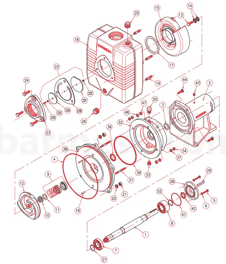
For repair parts please supply: Model Number and Serial as shown on Name Plate, and Part Description and Part Number as shown on the parts list.
Self Priming Frame Mounted Pum s BSP15 20 & 25ICU, Parts List
| Item | Part No. | Description | Qty | Material | ||
| 1 | 30400776 | Shaft | 1 | Stainless | ||
| 2 | 3040031 | Pedestal | 1 | Cast Iron | ||
| 3 | 92010014 | Slinger | 1 | Buna | ||
| 4 | 92010062 | 0-Ring | 1 | ■ | ♦ | Buna |
| 5 | 91010343C | Hex Head Screw 5/16-18UNC x 1.0″ lg. | 4 | Stainless | ||
| 6 | 91010060 | Lockwasher 5/16″ | 4 | Stainless | ||
| 7 | 31020022 | Inboard Bearing | 1 | ♦ | ||
| 8 | 31020044 | Outboard Bearing | 1 | ♦ | ||
| 9 | 31030156 | Shaft Seal | 1 | ■ | ♦ | C/CE/N/SS |
| 10 | 91010121 | Shim 0.010″ | 3 | ■ | ♦ | Stainless |
| 11 | 91010130 | Shim 0.031″ | 2 | ■ | ♦ | Stainless |
| 12 | 3140233 | Impeller 15CCE-ICU 6.0013 | 1 | Cast Iron | ||
| 3140226 | Bronze | |||||
| 3140234 | Impeller 20CCE-ICU 6.0013 | Cast Iron | ||||
| 3140227 | Bronze | |||||
| 3140235 | Impeller 25CCE-ICU 7.0013 | Cast Iron | ||||
| 3140228 | Bronze | |||||
| 13 | 91010349B | Hex Head Screw W-20UNF x 1.0″ SS | 1 | ■ | ♦ | Stainless |
| 14 | 91010081 | Shakeproof Washer 1/2″ SS | 2 | ■ | ♦ | Stainless |
| 15 | 3120040 | Volute 15-20CCE-ICU | 1 | Cast Iron | ||
| 3120036 | Bronze | |||||
| 3120041 | Volute 25CCE-ICU | Cast Iron | ||||
| 3120037 | Bronze | |||||
| 16 | 91010181 | Volute Pin | 2 | Steel | ||
| 17 | 92010122 | Volute Gasket | 1 | ■ | ♦ | Buna |
| 18 | 3090098 | Body | 1 | Cast Iron | ||
| 19 | 91010378C | Stud ‘/2″-13UNC x 2″ Igo. SS | 5 | Stainless | ||
| 20 | 91010062 | Lockwasher 1/2″ SS | 5 | Stainless | ||
| 21 | 91010415 | Hex Nut 1/2″ SS | 5 | ■ | Stainless | |
| 22 | Check Valve Assy | 1 | ■ | |||
| 22A | 3080007 | Weight 2%13 | 1 | Steel | ||
| 22B | 92010217 | Gasket | 1 | ■ | Neoprene | |
| 22C | 91010066 | Lockwasher ‘A” SS | 1 | Stainless | ||
| 22D | 91010407B | Round Hd Screw %”-20UNC x 1.0″ lg. | 1 | Stainless | ||
| 22E | 91010411C | Hex Nut 1/2″ SS | 1 | Stainless | ||
| 22 F | 3080012 | Weight 4″0 | 1 | Steel | ||
| 23 | 3050022 | Suction Flange | 1 | Cast Iron | ||
| 24 | 91010263 | Hex Head Screw W-13UNC x 1W | 3 | Steel | ||
| 25 | 93010141 | Pipe Plug 1″ NPT | 1 | Cast Iron | ||
| 26 | 93010141 | Pipe Plug if NPT | 1 | Cast Iron | ||
| 27 | 31010004 | Snap Ring | 1 | ♦ | Steel | |
| 28 | 3170022 | Bearing Cap | 1 | |||
| 29 | 30400633 | Shaft Key’/:’ x ‘A” x 21/2″ lg. | 1 | ♦ | Steel | |
| 31 | 91010374 | Stud 3/8″-16UNC x 2.00″ SS | 4 | Stainless | ||
| 32 | 3020054 | Coupling Head | 1 | Cast Iron | ||
| 33 | 93010149 | Pipe Plug 3/8″ NPT | 1 | Steel | ||
| 34 | 91010433 | Tuerca de 3/8″-16UNC SS | 4 | Stainless | ||
| 36 | 31010017H | Lip Seal (1.375″x1.828″x.312″) | 1 | ■ | ♦ | Brand CR |
| 37 | 91010061 | Lockwasher 3/8″ SS | 4 | Stainless | ||
| 38 | 3180064 | Seal Plate | 1 | Cast Iron | ||
| 39 | 92010066H | 0-Ring | 1 | ■ | ♦ | Buna N |
| 41 | 92010066G | 0-Ring | 1 | ♦ | Buna N | |
| 42 | 31150013 | Lip Seal (1.125″x1.562″x.312″) | 1 | ♦ | Brand CR | |
| 43 | 93010041 | Relief Fitting 1/8″ NPT | 1 | Steel | ||
| 44 | 91010348C | Hex Head Screw 7/16-14UNC x 2W lg. | 4 | Stainless | ||
| 47 | 91010071 | Lock washer 7/16″ | 4 | Stainless | ||
| 48 | 91010434 | Hex Nut 7/16″-14UNC | 4 | Stainless | ||
| 49 | 31010035 | Gear Oil, ISO VG68 | 4 oz. | |||
| 50 | 80062501 | Vented Plug | 1 | Steel | ||
| 51 | 91010043 | Grease, Lithium Soap Base, NGLI-2 | 4 oz. | |||
| 52 | 31010004 | Snap Ring | 1 | Steel | ||
Seal Kit (.): 4, 9, 10, 11, 13, 14, 17, 20, 21, 22B, 36, 39
Overhaul Kit (•): 4, 7, 8, 9, 10, 11, 13, 14, 22B, 27, 29, 36, 39, 41, 42, 43
For repair parts please supply: Model Number and Serial as shown on Name Plate, and Part Description and Part Number as shown on the parts list.
Troubleshooting Chart
![]() Always disconnect the pump from the electrical power source before handling.
Always disconnect the pump from the electrical power source before handling.
If the system fails to operate properly, carefully read instructions and perform maintenance recommendations.
| Symptom | Possible Causes) | Corrective Action |
| Little or no discharge and unit will not prime | 1. Casing not filled with water 2. Total head too high 3. Suction head higher than pump designed for 4. Impel ler partially or completely plugged 5. Hole or leak in the suction line 6. Foot-valve too small 7. Impel ler damaged 8. Foot-valve or suction line not submerged deep enough in water; pulling air 9.Insufficient inlet pressure or suction head 10. Suction piping too small 11. Casing gasket leaking 12. Suction or discharge line valves closed 13. Piping is fouled or damaged 14. Clogged strainer or foot-valve 15. Incorrect engine speed | 1. Fill pump casing. Using a foot-valve will extend pump life and facilitate immediate priming 2. Shorten suction head 3.Lower suction head, install foot-valve, and prime. 4. Disassemble the pump and dean out the impeller 5. Repair or replace the suction line 6. Match foot-valve to piping or install one size larger foot-valve 7. Disassemble the pump and replace the impeller B. Submerge lower in water 9. Increase inlet pressure by adding more water tank or increasing back pressure by turning gate valve on discharge line partially dosed position 10. Increase pipe size to pump inlet size or larger 11. Replace 12. Open 13. Clean or replace 14. Clean or replace 15. Increase speed |
| Loss of suction after satisfactory operation | 1. Air leak in the suction line 2. When the unit was last turned off, water siphoned out of the pump casing 3. Suction head higher than pump designed for 4.Insufficient inlet pressure or suction head 5. Clogged foot-valve, strainer, or pump 6. Defective wear plate(s) | 1. Repair or replace the suction line 2. Refill (reprime) pump casing before restarting 3.Lower suction head, install foot-valve and primer 4. Increase inlet pressure by adding more water tank or increasing back pressure by turning the gate valve on the discharge line to a partially dosed position 5. Unclog, clear, or replace as necessary 6. Replace |
| Pump overloads driver | 1. Total head lower than pump rating, unit delivering too much water 2. Specific gravity and viscosity of the liquid being pumped different than the pump rating 3. Speed to high | 1. Increase back pressure on the pump by turning the gate valve on the discharge line to a partially closed position that will not overload motor 2. Consult the factory 3. Check and correct, lower speed |
| The pump vibrates and/or makes excessive noise | 1. Mounting plate or foundation not rigid enough 2. Foreign material in pump causing unbalance 3. Impel ler bent 4. Cavitation present 5. Piping is not supported to relieve any strain on the pump assembly | 1. Reinforce 2. Disassemble pump and remove 3. Replace the impeller 4. Check the suction line for proper size and check the valve in the suction line if completely open, remove any sharp bends before the pump, and shorten the suction line 5. Make necessary adjustments |
| Pump runs but no fluid | 1. Faulty suction piping (air leak) 2. Pump located too far from the fluid source 3. Gate valve closed 4. Clogged strainer 5. Fouled foot-valve 6. Discharge height too great 7. Fouled impeller 8. Faulty mechanical seal | 1. Replace 2. Replace 3. Open 4. Clean or replace 5. Clean or replace 6. Lower the height 7. Clean or replace & Replace |
| Pump leaks at shaft | 1. Worn mechanical seal 2. Replacement seal not installed properly | 1. Replace 2. Follow Maintenance instructions carefully |
BARMESA PUMPS
FACTORY WARRANTY
Barnes Pumps warrants that products of our manufacture will be free of defects in material and workmanship under normal use and service for 18 months from the date of manufacture or 12 months from the installation date whichever occurs first. This warranty gives you specific legal rights, which vary from state to state.
This warranty is a limited warranty, and no warranty-related claims of any nature whatsoever shall be made against Barmesa Pumps, until the ultimate consumer or his/her successor notifies us in writing of the defect and delivers the product and/or defective part(s) freight prepaid to our factory or nearest authorized service station as instructed by Barmesa Pumps. THERE SHALL BE NO FURTHER LIABILITY, WHETHER BASED ON WARRANTY, NEGLIGENCE OR OTHERWISE. PRODUCT SHALL BE EITHER REPLACED OR REPAIRED AT THE ELECTION OF BARMESA PUMPS. Guarantees relating to performance specifications provided in addition to the foregoing material and workmanship warranties on a product manufactured by Barmesa Pumps, if any, are subject to possible factory testing. Any additional guarantees, in the nature of certified performance specifications or time frame, must be in writing and such writing must be signed by our authorized factory manager at the time of order placement and/or at the time of quotation. Due to inaccuracies in field testing and should, a conflict arises between the results of field testing conducted by or for the user, Barmesa Pumps reserves the right to have the product returned to our factory for additional testing.
This warranty shall not apply when damage is caused by (1) improper installation, (2) improper voltage, (3) lightning, (4) excessive sand or other abrasive material, (5) corrosion build-up due to excessive chemical content, or (6) uncontrollable acts of god. Any modification of the original equipment will also void the warranty. We will not be responsible for loss, damage or labor cost due to interruption of service caused by defective pumps, parts, or systems. Barmes Pumps will not accept charges incurred by others without our prior written approval.
This warranty is void if our inspection reveals the product was used in a manner inconsistent with normal industry practice and/or our specific recommendations. The purchaser is responsible for the communication of all necessary information regarding the application and use of the product. UNDER NO CIRCUMSTANCES WILL WE BE RESPONSIBLE FOR ANY OTHER DIRECT OR CONSEQUENTIAL DAMAGES, INCLUDING BUT NOT LIMITED TO TRAVEL EXPENSES, CONTRACTOR FEES, UNAUTHORIZED REPAIR SHOP EXPENSES, LOST PROFITS, LOST INCOME, LABOR CHARGES, DELAYS IN PRODUCTION, IDLE PRODUCTION, WHICH DAMAGES ARE CAUSED BY ANY DEFECTS IN MATERIAL AND/OR WORKMANSHIP AND/OR DAMAGE OR DELAYS IN SHIPMENT. THIS WARRANTY IS EXPRESSLY IN LIEU OF ANY OTHER EXPRESS OR IMPLIED WARRANTY. No rights extended under this warranty shall be assigned to any other person, whether by operation of law or otherwise, without our prior written approval.
IMPORTANT,
If you have a claim under the provision of the warranty, contact Barmesa Pumps or your
authorized Barmesa Pumps Distributor:
[email protected]
www.barmesapumps.com
![]()


