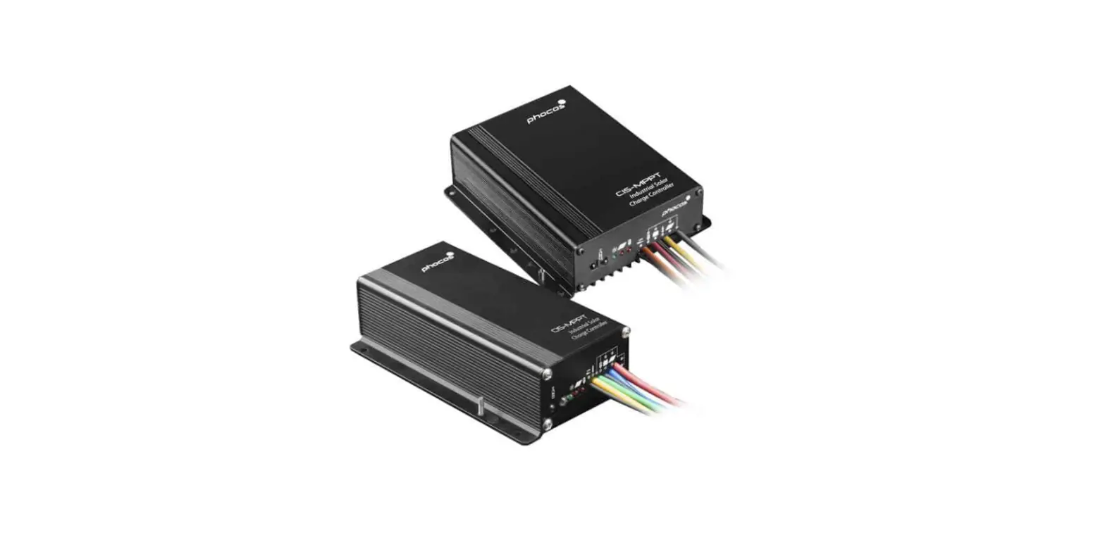
phocos CIS-N-LED 1400mA Charge Controller
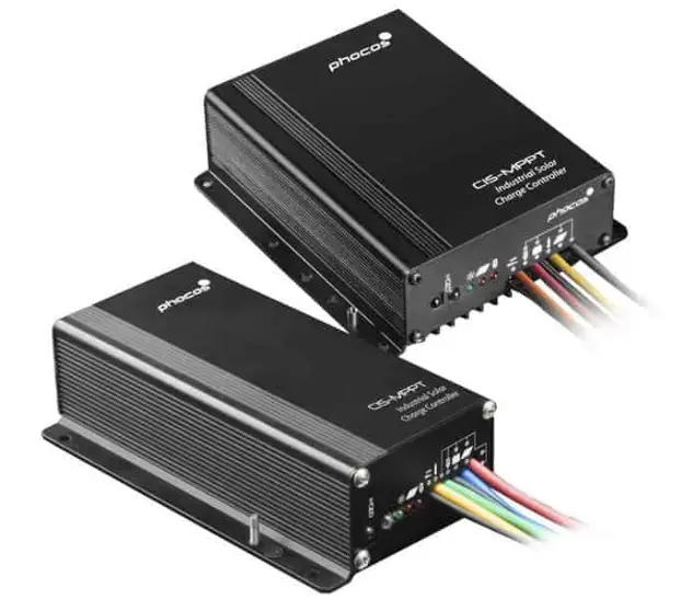
Please read the instructions carefully and thoroughly before using the product. It comes with a number of outstanding features, such as:
- LED driver inside, maximum output voltage up to 49 V
- Dimming function & double timer inside
- True color PWM dimming
- Type of protection: IP68, in 1.5 m water depth 72 hours
- Control unit (CIS-CU-LCD) to configure CIS-N-LED charge controller via infra-red data link
- External temperature sensor for temperature compensation of charging levels
- 4 stage charging (main, boost, equalization, float) for flooded battery, 3 stage charging (main, boost, float) for sealed battery
- Input signal for motion sensor (PIR)
General Safety Information
- This manual contains important installation, set up, and safety operating instructions.
- Please read the instructions and warnings in this manual carefully before beginning any installation.
- Please do not disassemble or attempt to repair Phocos products. Phocos charge controllers do not contain user-serviceable parts.
- Please observe all instructions with regards to external fuses/breakers as indicated.
- The information contained in this manual must be observed in its full extent. The manual contains information regarding installation, set up, and operation.
Maintenance and installation notes
- When installing or working on the PV system, please disconnect the PV (solar) modules from the charge controller first, to prevent any damages to the charge controller!
- Please verify that all cable/wire connections are done properly and well insulated and that no water or humidity can ingress. This avoids any bad or loose connections that would result in excessive heating or further damage.
- Please install a fuse or breaker near the battery before installing or adjusting the controller!
High voltage risks
- Never touch any electrical conductors in order to avoid electrical shock.
- Never work on live (energized) electrical equipment.
- When working around a battery, do not allow tools to bridge the battery terminals, or short circuit any part of the battery.
- Use only tools with insulated handles.
- Operation of this device may produce high voltage which can cause severe injuries or death in case of improper installation or operation of the device.
- PV modules can generate high DC voltages!
Mains and charging current risks
- Make sure the cables are always connected to the correct terminal. An electrical shock can be lethal. In general, any electric shock can be dangerous to your health.
CE labeling
The product is CE-compliant.
Connecting and Grounding
- Connect wires in the order as indicated in the system drawing 1, 2, 3, 4, 5, 6, 7 to avoid installation faults
- To avoid any voltage on the wires, first connect the wire to the controller, then to the battery, panel or load
- Make sure the wire length between battery and controller is as short as possible
- Maximum cable length from charge controller to LEDs: < 2m
- Be aware that the negative terminals of CIS-N-LED are connected together and therefore have the same electrical potential. If any grounding is required, always do this on the negative wires

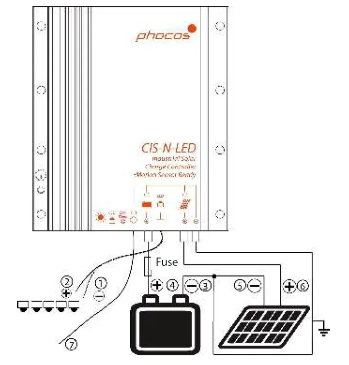
| Function | Cablemarker | Wiresize(cro section) | Color | |
| ① | NegativewireLED-output | – | AWG20(0.5mm2) | Blue |
| ② | PositivewireLED-output | – | AWG20(0.5mm2) | Red |
| ③ | Negativebateryterminal | COMMON- | AWG13(2.5mm2) | Black |
| ④ | Positivebateryterminal | BATERY+ | AWG13(2.5mm2) | Red |
| ⑤ | Negativepanelterminal | COMMON- | AWG13(2.5mm2) | Black |
| ⑥ | Positivepanelterminal | SOLAR+ | AWG13(2.5mm2) | Yelow |
| ⑦ | DIM-Overideinput | PIR | AWG24(0.25mm²) | Black |
Warning: The wires to the LEDs must not be connected to ground or anything else than the LEDs.
Display & Warning Functions
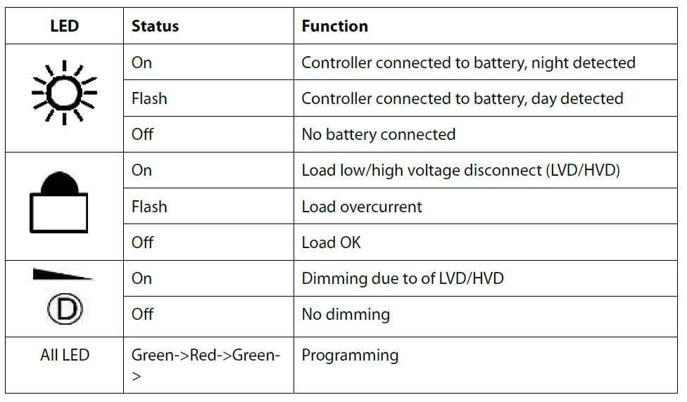
LED Driver Description
- Output voltage up to 49 V 5 to 15 LEDs in series for 12 V system, 10 to 15 LEDs in series for 24 V system
- Nominal output current: 350 mA, 600 mA, 700 mA, 1050 mA, 1400 mA, 2800 mA (depending on the type)
- Two timer inside to control LED brightness
- PIR Input: Switches the LED driver to the nominal output current (100% brightness). To be used with an external motion detector.
Dimming Function (output “logics”)
| No dimming | Dimming | Load of | |
| Timer1 | on | on | of |
| Timer2 | on | of | N/A |
The timer and dimming settings can be adjusted using the CIS-CU-LCD (Infrared remote control) or MXI-IR (Infrared to USB adapter) and CISCOM (PC-program).
PIR-Dimming override input: (0-0.5 V Off, 4-30 V On)
- Input for a signal from a motion sensor (PIR), to override the dimming and set the light to full brightness in case a person is detected.
- In this way, one can set a low dimming level to ensure a minimum light level, for sufficient orientation and to save energy.
- When a motion is detected, the light is switched to 100%.
- The duration of the activation has to be adjusted on the motion sensor.
Night-Light Function
The CIS-N-LED controller comes with a sophisticated night-light function. It controls the load output at night and is widely programmable.
There are 3 operating modes available: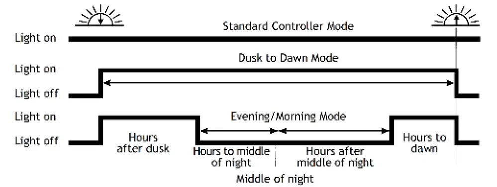
Standard Controller, Dusk to Dawn and Evening/Morning modes.
“Middle of night” is detected automatically as the midpoint between dusk and dawn, no setting of a clock is required. It may take several days until the controller has “learned” the middle of the night precisely. “Middle of night” may be different from 12:00 midnight depending on your location.
The controller recognizes day and night based on the solar array open circuit voltage.
This day/night threshold can be adjusted by programming according to local light conditions and the solar array used.
Testing Function
By pushing the “Test Button” on the CIS-CU-LCD (control unit), the LED-driver will be switched “on” for one minute.
Remark: If pressing the button causes a load disconnect event (LVD/SOC, overcurrent) the load will be switched off immediately.
Safety Features
| Solarterminal | Battery terminal | LED-output | PIR-input | |
| Reverse polarity | Protected(1) | Protected(1) | N/A | Protected |
| Shortcircuit(2) | Protected | Protected(3) | Not protected | Protected |
| Overcurrent | N/A | N/A | N/A | N/A |
| Reverse current | Protected(4) | N/A | N/A | N/A |
| Overvoltage | Max.50V(5) | Max.36V | Switches above15.5/31.0 Vbateryvoltage | Max.30V (50Vshort time) |
| Undervoltage | N/A | N/A | Switchesof | N/A |
| Over- temperature | ReducesthechargingcurentbyPWMifover temperature occurs and switched of the load if the temperature reaches a high level. | N/A | ||
- Upanel-Battery is limited to 40 V.
- Short circuit: >3x – 20x nominal current.
- Battery must be protected by a fuse, or it can be permanently damaged in case of a short
circuit.
Remark: It is recommendable to use a fuse which amperage corresponds to the nominal current of the charge controller. E.g. CIS-N-LED (10 A) needs a 10 A fuse. - Reverse current through solar panel is blocked by serial MOSFET. This function is tested and activated approx. one time in 1min +/-5s.
- The solar panel voltage should not exceed this limit for a longer period of time as surge protection is present by varistor.
WARNING: The combination of different error conditions may cause damage to the controller. Always remove the error before you continue connecting the controller!
Low Voltage Disconnect Function (LVD)
- State of charge (SOC) controlled: Disconnect at
- 11.00/22.00 V to 11.70/23.40 V(SOC1), 11.12/22.24 V to 11.76/23.52 V(SOC2),
- 11.25/22.50 V to 11.83/23.63 V(SOC3), 11.38/22.72 V to 11.89/23.78 V(SOC4),
- 11.51/23.02 V to 11.96/23.92 V(SOC5), 11.64/23.28 V to 12.02/24.04 V(SOC6).
- Voltage controlled (LVD):
Disconnect at a fixed voltage between 11.0/22.0 V and 11.9/23.8 V (Step 0.1/0.2 V).
Note: Battery voltage must be below setting for longer than 2 minutes for LVD to take effect.
Factory Settings
You can configure CIS-N-LED charge controllers via the control unit (CIS-CU-LCD). See CIS-CU-LCD manual for details.
| Factory setings | |
| Load mode | Standard controller (night light of) |
| Lowvoltagedisco nect | SOC4 |
| Baterytype | GEL |
| Dimmingvalue | 50% |
| Nightdetectlevel | 8/16V(1) |
| Timer1eveninghours | 0h |
| Timer1morninghours | 0h |
| Timer 2 evening hours | 0h |
| Timer2morninghours | 0h |
PV panel open circuit voltage: Day level = night level + 1.5/3.0 V
Technical Data
Note: The two voltage levels before/after the slash are valid for 12 V and 24 V systems respectively.
| TechnicalData | CIS-N-LED 350mA | CIS-N-LED 6 0mA | CIS-N-LED 7 0mA | CIS-N-LED 1050mA | CIS-N-LED 14 0mA | CIS-N-LED 28 0mA |
| Systemvoltage | 12/24Vautorecognition | |||||
| Max.chargecurent | 10A(15A,≤50°C*) | 20A(30A,≤50°C*) | ||||
| Floatcharge | 13.8/27.6V(25°C) | |||||
| Maincharge | 14.4/28.8V(25°C),0.5h(daily) | |||||
| Bostcharge | 14.4/28.8V(25°C),2h Activation:bateryvoltage<12.3/24.6V | |||||
| Equalization | 14.8/29.6V(25°C),2h Activation:bateryvoltage<12.1/24.2V (atleastevery30days) | |||||
| D epdischarge protection Cut-ofvoltage | 1.0-12.02/2.0-24.04VbySOC
1.0/2.0-1.9/23.8Vbyvoltage(adjustablestep0.1/0.2V) | |||||
| Reconectlevel | 12.8/25.6V | |||||
| Overvoltage protection | 15.5/31.0V |
| Undervoltage protection | 10.5/21.0V |
| Max.panelvoltage (Surgeprotectionby varistor) | 50V |
| Temperature compensation (Chargevoltage) | -4.2mV/K(2Vcel) |
| Max.self consumption | 5–8mA |
| Grounding | Negativegrounding |
| Ambient temperature | −40to+60°C |
| Max.altitude | 4, 0mabovesealevel |
| Baterytype | Leadacid(GEL,AGM,floded) |
| Adjustmentrange: Evening/morning | 0–15h/0–14h |
| hours Nightdetection Daydetection | 2.5–10.0V/5.0–20.0V(adjuststep0.5/1.0V) 4.0– 1.5V/8.0–23.0V(adjuststep0.5/1.0V) | |
| Wire length | 20cm | |
| Dimensions (WxHxD) | 82x97x20mm | 92x 9x 2mm |
| Weight | 210g | 250g |
| Wirecro section | AWG13(2.5mm2) | |
| Type of protection | IP68(1.5m,72h) | |
| LEDdriverdata | CIS-N-LED 350mA | CIS-N-LED 6 0mA | CIS-N-LED 70mA | CIS-N-LED 1050mA | CIS-N-LED 14 0mA | CIS-N-LED 28 0mA* |
| Output voltage | 15Vto49Vfor12Vsystem(5to15LEDsinseries) 30Vto49Vfor24Vsystem(10to15LEDsinseries) | |||||
| Nominal output curentperstring | 350mA | 60mA | 70mA | 1050mA | 140mA | 280mA |
| Max.load power | 15W | 25W | 30W | 45W | 60W | 60W(12V)/ 120W(24V) |
| Dimming level | 0–10%(adjuststep10%) |
| PIR-input | 4V.30Vwithrespectobaterynegative,>=0.7mA; limited protection up to 50V |
- 12 V: 15-24 V (5-8 LEDs in series)
- Without simultaneous LED output current at a maximum ambient temperature of 50°C Please notice:
The CIS-N-LED features integrated overtemperature protection that will reduce the average charge current in case of too high temperatures.
Liability Exclusion
The manufacturer shall not be liable for damages, especially to the battery, caused by use other than as intended or as mentioned in this manual or if the recommendations of the battery manufacturer are neglected. The manufacturer shall not be liable if there has been service or repair carried out by any unauthorized person, unusual use, wrong installation, or bad system design.
Subject to change without notice. Version: 20150130 Made in one of the following countries: Germany – China – Bolivia – India
Phocos AG – Germany www.phocos.com


