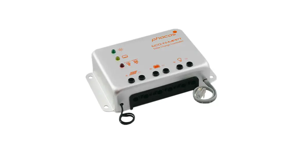
phocos ECO-N-MPPT 85 15A 12 24VDC MPPT Charge Controller User Manual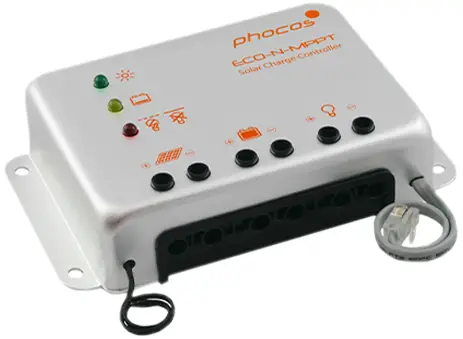
Dear Customer,
Congratulations on buying your Phocos product! Please read the instructions carefully and thoroughly before using the product. It comes with a number of outstanding features, such as:
- Outstanding system efficiency (max. 98%) thanks to integrated Maximum Power Point Tracker technology (MPPT)
- Maximizes power output & reduces system costs
- IP68 casing, IP21 terminals
- Compatible with 60-cell PV modules
- 12/24 V DC systems
General Safety Information
This manual contains important installation, set up, and safety operating instructions.
Please read the instructions and warnings in this manual carefully before beginning any installation.
Please do not disassemble or attempt to repair Phocos products. Phocos’ charge controllers do not contain user serviceable parts.
Please observe all instructions with regard to external fuses/breakers as indicated.
The information contained in this manual must be observed in its full extent. The manual contains information regarding installation, set up, and operation.
Please read this manual carefully before using the product, and pay special attention to the safety recommendations in it.
Maintenance and installation notes
When installing or working on the PV system, please disconnect the PV (solar) modules from the charge controller first, to prevent any damages to the charge controller!
Please verify that all cable/wire connections are done properly and are well insulated and that no water or humidity can ingress in order to avoid any bad or loose connections that would result in excessive heating or further damage.
Please install a fuse or breaker near the battery before installing or adjusting the controller!
When connecting inductive loads (motors, relays, etc.) a freewheel diode must be connected in parallel to the loads in the reverse biased direction.
High voltage risks
Never touch any electrical conductors to avoid electrical shock.
Never work on live (energized) electrical equipment.
When working around a battery, do not allow tools to bridge the battery terminals, or short circuit any part of the battery.
Use only tools with insulated handles.
Operation of this device may produce a high voltage which could cause severe injuries or death in case of improper installation or operation of the device.
PV modules can generate high DC voltages!
Mains and charging current risks
Make sure the cables are always connected to the correct terminal. An electrical shock can be lethal. In general, any electric shock can be dangerous to your health.
CE labeling
The product is CE compliant.
Connecting and Grounding
The controller is intended for indoor use only. Protect it from direct sunlight and place it in a dry environment. Never install it in humid rooms (like bathrooms). The controller warms up during operation, and should therefore be installed on a non flammable surface only.
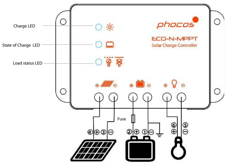
- Connect wires in indicated order 1 2 3 4 5 6 to avoid any installation faults
- To avoid any damaging voltage on the wires, first connect the wire to the controller, then to the battery, to the panel or to the load
- Minimum recommended wire size: 4 mm²
- Make sure the wire length between battery and controller is as short as possible
- Be aware that the negative terminals of the ECO-N-MPPT 85/15 are connected together and therefore have the same electrical potential. If any grounding is required, always do this on the negative wires.
- When connecting inductive loads (motors, relays, etc.) a freewheel diode must be connected in parallel to the loads in the reverse biased direction.
- Inverters should always be connected directly to the battery due to their high inrush currents.
Starting up the controller
Self Test
As soon as the controller is supplied with power from the battery, it starts a self test routine. Then the display changes to normal operation.
System Voltage
The controller adjusts itself automatically to 12 V or 24 V system voltage. As soon as the voltage at the time of start-up exceeds 18 V, the controller assumes a 24 V system. If the battery voltage is not within the normal operation range at start-up, a status display according to the section ERROR DESCRIPTION occurs.
Battery Type
The ECO-N-MPPT 85/15 has no equalization charge and is therefore suitable for lead-acid batteries with liquid electrolyte (vented batteries) and leadacid batteries with solid electrolyte (GEL or AGM batteries). In case of any doubts consult your local dealer.
LED indications & warning functions
| LED | Status | Function |
 | On | Controller connected to battery, night detected |
| Flash | Controller connected to battery, day detected | |
| Of | No battery connected | |
 | On | Battery SOC low |
| Flash | Battery SOC very low | |
| Of | Battery OK |
 | On | Load low/high voltage disconnect (LVD/HVD) |
| Flash | Load overcurrent, over load or short-circuit | |
| Off | Load OK |
Safety Features
| PV terminals | Battery terminals | Load terminals | |
| Reverse polarity | Protected(1) | Not protected(2) | Protected(3) |
| Short-circuit(4) | Protected | Protected(5) | Switches off immediately |
| Over current | Limited | – | Switches off with a delay(6) |
| Reverse current | Protected(7) | – | – |
| Over voltage | Max.85V(8) | Max.85V | Switches off above 15.5/31.0V |
| Under voltage | – | – | Switches off |
| Over temperature | Reduces the charging current if over temperature occurs and switches off the load if the temperature reaches a high level. | ||
- Panels are short circuited by diodes. The controller can therefore only be subjected to these conditions for a limited time. A battery connected to the panel terminals in reverse polarity will instantly cause a damage to the controller.
- A battery fuse is necessary to protect the ECO-N-MPPT 85/15 from getting damaged by reverse polarity connection on the battery terminals.
- The controller can protect itself, but any connected loads might be damaged.
- Short-circuit: >3x – 20x nominal current.
- The battery must be protected by a fuse, or it might be permanently damaged in case of short-circuit.
- >200% nominal current: disconnects with 3s delay,
- MPPT switches off when detecting reverse current.
- At voltages above 85 V the MPPT will stop charging.
WARNING: The combination of different error conditions may cause damage to the controller. Always remove the fault condition before you continue connecting the controller!
Low Voltage Disconnect Function (LVD)
The charge controller is equipped with a low voltage disconnection function to protect the battery against a deep discharge: This function is controlled by the voltage, and automatically switches off the load output at a battery voltage lower than 11.0/22.0 V. As soon as the battery reaches a voltage of 12.8/25.6 V, the load output is switched on again.
Note: Battery voltage must be below adjusted setting for longer than 2 minutes before LVD occurs.
Note: Voltage levels before/after the slash are valid for 12 V and 24 V systems respectively (valid for the charge controllers presented in this manual).
Error Description
| Error | Display | Reason | Remedy |
| Loads are not supplied with energy |
| Battery is low | Load will reconnect as soon as battery is recharged. |
 Red LED flashing | Over current/Shortcircuit of loads/Over temperature protect | Switch off all loads.Remove shortcircuit. Controller will switch on load automatically after max1 minute. |

| Loads are not supplied with energy | 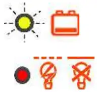 Red LED on and yellow LED fast flashing | Battery voltage>15.5/31.0V | Check if other sources over charge the battery. If not, controller is damaged. |
| Battery cables or battery f use damaged, battery shows high internal resistance |
Check battery wires,fuses and battery. | ||
| Battery is empty after a short time |
| Battery show slow capacity |
Change battery |
| No battery connected |  Green LED off | No battery connected |
Connect battery |
| Battery reverse polarity |  Red LED on | Battery is connected with reverse polarity | Remove reverse polarity |
 Red LED on
Technical Data
Note: The voltage levels before/after the slash are valid for 12 V and 24 V systems respectively.
| Technical Data | ECO-N-MPPT85/15 |
| System voltage | 12/24Vauto recognition |
| Max.charge current/loadcurrent | 15A |
| Max.usablePVpower | 25W@12V,450W@24V |
| Max.PVaraypower | 250Wp@12V,50 Wp@24V |
| Floatcharge | 13.8/27.6V(25°C) |
| Maincharge | 14.4/28.8V(25°C),0.5h(daily) |
| Bostcharge | 14.4/28.8V(25°C),for 2h, activation: battery voltage<12.3/24.6V |
| Equalization charge | 14.8/29.6V(25°C),for2h;activation: battery voltage<12.1/24.2V(atleastevery30days) |
| Deep discharge protection, Cut-off voltage | 11.0/2.0V |
| Reconnect level | 12.8/25.6V |
| Over voltage protection | 15.5/31.0V |
| Under voltage protection | 10.5/21.0V |
| Max.PV voltage | 85V |
| Min.PV voltage | 17/34V |
| Temperature compensation (charge voltage) | -25mV/K@12V/-50mV/K@24V |
| Idle self-consumption | 15mAat12V,8mAat24V |
| Grounding | Common negative pole(for grounding purposes) |
| Ambien temperature | −40to+60°C |
| Max.altitude | 4,00 m abovesea level |
| Battery type | Lead acid (GEL,AGM,floded) |
| Maximum wire cross section | 16mm²(AWG6) |
| Dimensions (WXHXD) | 147x90x31mm/5.8×3.5×1.2in |
| Weight | 1,10kg/2,43Ibs |
| Type of protection | IP68 casing, IP21 terminals |
Liability Exclusion
The manufacturer shall not be liable for damages, especially on the battery, caused by use other than as intended or as mentioned in this manual or if the recommendations of the battery manufacturer are neglected. The manufacturer shall not be liable if there has been service or repair carried out by any unauthorized person, or for unusual use, wrong installation, or bad system design.
Specifications are subject to change without notice.
Version: 20190408
Made in China
 ISO9001
RoHS
Phocos AG
Magirus-Deutz-Str. 12
89077 Ulm, Germany
Phone +49 731 9380688-0
Fax +49 731 9380688-50
www.phocos.com
[email protected]


 Solar Mppt Charge Controller User Manual")


