phocos CIS-N Solar Charge Controller User Manual
Please read the instructions carefully and thoroughly before using the product. It comes with a number of outstanding features, such as:
- Case protection: IP68 protection, in 1.5 m water depth 72 hours.
- Dimming function
- Control unit (CIS-CU) to configure CIS charge controller via infra-red data link
- External temperature sensor for temperature compensation of charge voltages
- Widely programmable
- 3 stage charging (boost, equalization, float) for flooded battery, 2 stage charging (boost, float) for sealed battery
- Automatic recognition of system voltage 12/24 V
General Safety Information
![]() This manual contains important installation, set up, and safety operating instructions.
This manual contains important installation, set up, and safety operating instructions.
Please read the instructions and warnings in this manual carefully before beginning any installation.
Please do not disassemble or attempt to repair Phocos products. Phocos charge controllers do not contain user serviceable parts.
Please observe all instructions with regards to external fuses/breakers as indicated.
The information contained in this manual must be observed in its full extent. The manual contains information regarding installation, set up, and operation.
Please read this manual carefully before using the product, and pay special attention to the safety recommendations in it.
Maintenance and installation notes
When installing or working on the PV system, please disconnect the PV (solar) modules from the charge controller first, to prevent any damages to the charge controller!
Please verify that all cable/wire connections are done properly and well insulated and that no water or humidity can ingress. This avoids any bad or loose connections that would result in excessive heating or further damage.
Please install a fuse or breaker near the battery before installing or adjusting the controller!
High voltage risks
Never touch any electrical conductors to avoid electrical shock.
Never work on live (energized) electrical equipment.
When working around a battery, do not allow tools to bridge the battery terminals, or short circuit any part of the battery.
Use only tools with insulated handles.
Operation of this device may produce a high voltage which could cause severe injuries or death in case of improper installation or operation of the device.
PV modules can generate high DC voltages!
Mains and charging current risks
Make sure the cables are always connected to the correct terminal. An electrical shock can be lethal. In general, any electric shock can be dangerous to your health.
CE labeling
The product is CE compliant.
Connecting and Grounding
- Connect wires in order indicated 1 2 3 4 5 6 7 to avoid installation faults.
- To avoid any voltage on the wires, first connect the wire to the controller, then to the battery, panel or load.
- Recommended minimum wire size: CIS05: 1.5 mm2; CIS10: 2.5 mm2; CIS20: 4 mm2.
- Make sure the wire length between battery and controller is as short as possible.
- Be aware that the positive terminal of CIS are connected together and therefore have the same electrical potential. If any grounding is required, always do this on the positive wires.
- Some equiptment, like relays, gates or motors, can damage the controller by magnetic induction, when it switches off. To prevent this, reverse connect the diode (such as 1N5401 .. 1N5408) between LOAD positive and LOAD negative.
| Function | Cablemarker | Wiresize(crossection) | Color | |
| 1 | Positive battery terminal | COMMON+ | AWG13(2.5mm2) | Red |
| 2 | Negative battery terminal | BATERY- | AWG13(2.5mm2) | Black |
| 3 | Positive panel terminal | COMMON+ | AWG13(2.5mm2) | Red |
| 4 | Negative panel terminal | SOLAR- | AWG13(2.5mm2) | Blue |
| 5 | Positive load terminal | COMMON+ | AWG13(2.5mm2) | Red |
| 6 | Negative load terminal | LOAD- | AWG13(2.5mm2) | Gren |
| 7 | Dimming signal terminal | – | AWG24(0.25mm2) | Black |
To dimming terminal of lamp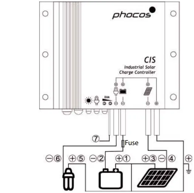
Display & Warning Functions
| LED | Status | Function |
 | 0n | Controller connected to battery, night detected |
| Flash | Controller connected to battery, day detected | |
| Of | No battery connected | |
 | On | Load low/high voltage disconnect (LVD/HVD) |
| Flash | Load over curent | |
| Of | Load OK | |
| On | Dimming be cause of LVD/HVD | |
| Of | Time controled dimming | |
| All LED | Gren->Red->Gren-> | Programming |
Night-Light Function
The CIS controller comes with a sophisticated night-light function. It controls the load output at night and is widely programmable.
There are 3 modes available:
Standard Controller, Dusk to Dawn and Evening/Morning modes.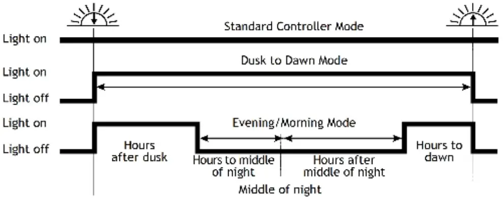
“Middle of night” is detected automatically as the midpoint between dusk and dawn, no setting of a clock is required. It may take several days until the controller has “learned” the middle of the night precisely. “Middle of night” may be different from 12:00 midnight depending on your location.
The controller recognizes day and night based on the solar array open circuit voltage. This day/night threshold can be modified according to local light conditions and the solar array used.
Testing Function
Pushing the test button on the CIS-CU (Control Unit) will switch on load terminal for 2 minutes. If pressing the button causes a load disconnect event (LVD/SOC, over current) the load will be switched off.
Safety Features
| Solar terminal | Battery terminal | Load terminal | |
| Reverse polarity | Protected(1) | Protected(1) | Protected(2) |
| Short circuit | Protected | Protected(3) | Switches of immediately |
| Over current | N/A | N/A | Switches of with delay |
| Reverse current | Protected | N/A | N/A |
| Over voltage | Max.5 V(4) | Max.40V | Switches of above 15.5 V/31.0 V |
| Under voltage | N/A | N/A | Switches of |
| Over temp. | Reduces the charging current by PWM if over temperature occurs and switches of the load if the temperature reaches a high level. | ||
- Controller can not protect itself in a 24 V system; U panel-U battery is limited to 40 V.
- Controller can protect itself, but loads might be damaged.
- Battery must be protected by fuse, or battery will be permanently damaged.
- The solar panel voltage should not exceed this limit for a long time as voltage protection is done by a varistor.
WARNING: The combination of different error conditions may cause damage to the controller.
Always remove the error before you continue connecting the controller!
Low Voltage Disconnect Function (LVD)
- State of charge (SOC) controlled: Disconnect at
11.00/22.00 V to 11.70/23.40 V(SOC1), 11.12/22.24 V to 11.76/23.52 V(SOC2), 11.25/22.50 V to 11.83/23.63 V(SOC3), 11.38/22.72 V to 11.89/23.78 V(SOC4), 11.51/23.02 V to 11.96/23.92 V(SOC5), 11.64/23.28 V to 12.02/24.04 V(SOC6) . - Voltage controlled (LVD): Disconnect at a fixed voltage between 11.0/22.0 V and 11.9/23.8 V (Step 0.1 V)
Note: The two voltage levels before/ after the slash are valid for 12 V and 24 V systems respectively.
Factory Settings
You can configure CIS charge controllers via the Control Unit (CU). See CU manual for details.
| Factory setting | |
| Load mode | Standard controller |
| Low voltage disconnect | SOC4 |
| Battery type | Sealed |
| Dimming value | 50% |
Liability Exclusion
The manufacturer shall not be liable for damages, especially on the battery, caused by use other than as intended or as mentioned in this manual or if the recommendations of the battery manufacturer are neglected. The manufacturer shall not be liable if there has been service or repair carried out by any unauthorized person, unusual use, wrong installation, or bad system design.
Technical Data
| Nominal voltage | 12/24 V, automatic recognition |
| Boost voltage | 14.4/28.8 V (25 °C), 2 h |
| Equalization voltage | 14.8/29.6 V (25 °C), 2 h |
| Float voltage | 13.8/27.6 V (25 °C) |
| Load disconnect voltage | 11.00-12.02 V/22.00-24.04 V By SOC 11.0-12.0 V/22.0-24.0 V By voltage |
| Load reconnect voltage | 12.8/25.6 V |
| Max. panel voltage | 50 V @ 24 V / 30 V @ 12 V |
| Evening hours /Morning hours | 0-15 hours / 0-14 hours |
| Dimming value | 0…100 % output power |
| Dimming output voltage | 0 V to 10 V relative to battery minus |
| Night/day detect | 2.5-10 V |
| Battery type | Flooded, sealed |
| Temp. Compensation | 4.2 mV/K per cel |
| Max. solar current | 5/10/20 A, According to model @ 60 °C |
| Max. load current | 5/10/20 A, According to model @ 60 °C |
| Dimensions | 82 x 58 x 20 mm |
| Wire size | AWG 13 (2.5 mm2) |
| Typical power consumption | Lower than 8/10mA |
| Ambient temp. range** | -40 to +60 °C |
| Case protection | IP68 (1.5 m, 72 h) |
| Max altitude / Weight | 4000 m / 150 g |
** :At 60°C CIS can only have full current on panel or load, not together.
Support
Subject to change without notice. Version: 20141113
Made in one of the following countries:
Germany – China – Bolivia – India
Phocos AG – Germany www.phocos.com
ISO9001