phocos ECO-N Solar Charge Controller User Manual
IMPORTANT SAFETY INSTRUCTIONS
This manual contains important installation, set up, and safety operating instructions.
Please read the instructions and warnings in this manual carefully before beginning any installation.
Please do not disassemble or attempt to repair Phocos products. Phocos charge controllers do not contain user serviceable parts.
Please observe all instructions with regards to external fuses/breakers as indicated.
The information contained in this manual must be observed in its full extent. The manual contains information regarding installation, set up, and operation.
Please read this manual carefully before using the product, and pay special attention to the safety recommendations in it.
Maintenance and installation notes
When installing or working on the PV system, please disconnect the PV (solar) modules from the charge controller first, to prevent any damages to the charge controller!
Please verify that all cable/wire connections are done properly and well insulated and that no water or humidity can ingress. This avoids any bad or loose connections that would result in excessive heating or further damage.
Please install a fuse or breaker near the battery before installing or adjusting the controller!
High voltage risks
Never touch any electrical conductors to avoid electrical shock.
Never work on live (energized) electrical equipment.
When working around a battery, do not allow tools to bridge the battery terminals, or short circuit any part of the battery.
Use only tools with insulated handles.
Operation of this device may produce a high voltage which could cause severe injuries or death in case of improper installation or operation of the device.
PV modules can generate high DC voltages!
Mains and charging current risks
Make sure the cables are always connected to the correct terminal. An electrical shock can be lethal. In general, any electric shock can be dangerous to your health.
CE labeling
The product is CE compliant.
Connecting and Grounding
The controller is intended for indoor use only. Protect it from direct sunlight and preferrably place it in a dry environment. Please verify that all cable/wire connections are done properly and well insulated and that no water or humidity can ingress. This avoids any bad or loose connections that would result in excessive heating or further damage. The controller measures the ambient temperature to determine the charging voltage. Controller and battery must be installed in the same room. The controller warms up during operation, and should therefore be installed on a non flammable surface only. Connect the controller by following the steps described below to avoid installation faults.
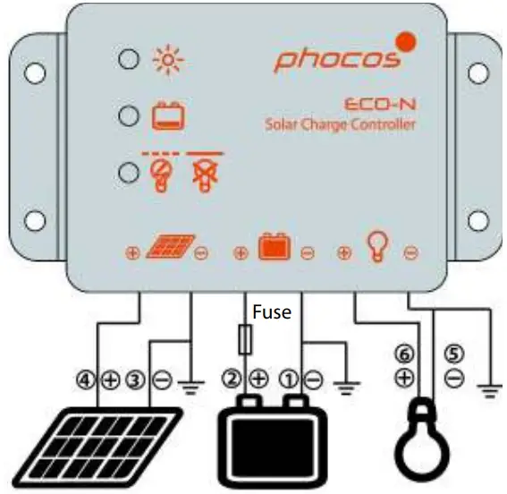
- Observe the following connection sequence when installing the system:
- Connect the battery to the charge controller – plus and minus.
- Connect the photovoltaic modules to the charge controller – plus and minus.
- Connect the load to the charge controller – plus and minus. Follow the reverse procedure when uninstalling!
- Additionally, to avoid any voltage on the wires, first connect the wire to the controller, then to the battery, photovoltaic modules. But for load, first connect the wire to the load, then to the controller.
- Recommended minimum wire size: 4 mm2;
- Make sure the wire length between battery and controller is as short as possible.
- Be aware that all negative connections of the ECO-N controller are common and therefore have the same electrical potential. If any grounding is required, always do this on the negative wire.
- When connecting inductive loads (motors, relays, etc.), a freewheel diode must be connected in parallel to the loads in the reverse biased direction.
- Due to their high inrush currents, large inverters should always be connected directly to the battery.
REMARK: If the device is used in a vehicle which has the battery negative pole connected to the chassis, than any loads connected to the controller must not have an electric connection to the car body. Otherwise the Low Voltage Disconnect function and the electronic fuse function of the controller will become impaired (short circuited).
REMARK: Mind the recommendations of your battery manufacturer. We strongly recommend connecting a fuse directly to the battery pole to protect any short circuit on the battery wiring. The fuse must match/attend the nominal current of the charge controller: 15A for ECO-N.
Starting up the controller
Self Test
As soon as the controller is supplied with power either from the battery, it starts a self test routine. Then the display changes to normal operation.
System Voltage
The controller is intended for use on 12 V systems. If the battery voltage is not within the normal operation range at start-up, a display status indication as presented in the section ERROR DESCRIPTION occurs.
Battery Type
The ECO-N charge controllers do not provide an equalization charge, and therefore are suitable for use with lead acid batteries with liquid electrolyte (vented battery) and lead acid batteries with immobilized electrolyte (GEL or AGM type). In case of any doubts consult your dealer.
Recommendations for Use
The controller warms up during normal operation.
The controller does not need any maintenance or service. Remove dust with a dry tissue.
It is important that the battery gets fully charged frequently (at least weekly).
Otherwise the battery will permanently be damaged.
A battery can only be fully charged if not too much energy is drawn during the charging process. Keep that in mind, especially when you install additional loads.
Display Functions in normal operation
The controller is equipped with 3 LEDs to display the operating status.
In normal operation, the controller shows the charging status, the battery SOC status and the load output status.
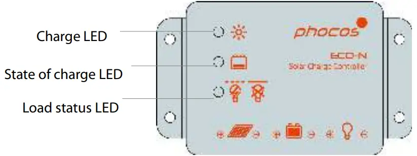
Charge display

Controller connected to battery, no sunlight over longer period(Green LED on)

Controller connected to battery, day detected (Green LED flashes)

No battery connected (Green LED off)
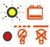
Battery SOC display
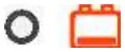
OK (Yellow LED off)

Low (Yellow LED on)

Very low (Yellow LED flashes)
When the battery voltage is indicated as low, it is recommended to use the remaining energy economically. The charge controller will subsequently switch off the load.
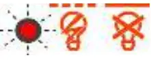
Load status display
In case of deep discharge or overload/short-circuit of load, the load output is switched off. This is indicated by:

Normal operation (Red LED off)

Low voltage disconnect High voltage disconnect (Red LED blank)

Overload or short-circuit of load (Red LED flashing)
Low Voltage Disconnect Function
The charge controller is equipped with a low voltage disconnection function to protect the battery against a deep discharge: This function is controlled by the voltage, and automatically switches off the load output at a battery voltage lower than 11.0 V. As soon as the battery reaches a voltage of 12.8 V, the load output is switched on again.
Safety Features
| PV terminals | Battery terminals | Load terminals | |
| Reverse polarity | Protected | Warning: Red LED on | Protected (1) |
| Short circuit (2) | Protected | Protected (3) | Switches off immediately |
| Overcurrent | — | — | Switches off with a delay (4) |
| Reverse current | Protected | — | — |
| Overvoltage | Max. 30 V | Max. 30 V | Switches off above 15.5 V |
| Undervoltage | — | — | Switches off |
| Over- temperature | Reduces the charging current if over temperature occurs and switches off the load if the temperature reaches high level. | ||
- Controller can protect itself, but any connected loads might be damaged.
- Short circuit: >4x – 6x nominal current.
- Battery must be protected by a fuse, or it might be permanently damaged in case of short circuit.
- >200% nominal current: disconnect with 3s delay
WARNING: The combination of different error conditions may cause damage to the controller. Always remove the fault condition before you continue with connecting the controller!
Error Description
| Error | Display | Reason | Remedy |
| Loads are not supplied with energy |  Red LED on |
Battery is low | Load will reconnect as soon as battery is recharged. |
 Red LED flashing | Overcurrent/ Short circuit of loads/Over temperature protect | Switch off all loads. Remove short circuit. Controller will switch on load automatically after max 1 minute. |
 Red LED on and yellow LED fast flashing | Battery voltage >15.5 V | Check if other sources over charge the battery. If not, controller is damaged. | |
| Battery cables or battery fuse damaged, battery shows high internal resistance |
Check battery wires, fuses and battery. | ||
| Battery is empty after a short time |  Red LED on | Battery shows low capacity | Change battery |
| No battery connected |  Green LED off | No battery connected | Connect batteries |
| Battery reverse polarity |  Red LED on | Battery is connected with reverse polarity | Remove reverse polarity |
Technical Data
| Technical Data | ECO-N |
| System voltage | 12 V |
| Max. charge current | 10 A** |
| Max. load current | 10 A** |
| Float charge | 13.8 V (25 °C) |
| Main charge | 14.4 V (25 °C), 0.5 h (daily) |
| Boost charge | 14.4 V (25 °C), 2 h Activation: battery voltage < 12.3 V |
| Overvoltage protection | 15.5 V |
| Deep discharge protection, Cut-off voltage | 11.0 V |
| Reconnect level | 12.8 V |
| Undervoltage protection | 10.5 V |
| Max. PV panel voltage | 30 V |
| Max. battery voltage | 30 V |
| Temperature compensation(Charge voltage) | −4.2 mV/K per cell |
| Self consumption | < 5 mA |
| Grounding | Negative grounded |
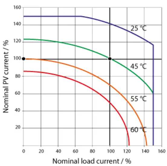
| Ambient temperature | −40 to +60 °C |
| Max. altitude | 4,000 m above sea level |
| Battery type | Lead acid (GEL, AGM, flooded) |
| Dimensions (WXHXD) | 87 x 51 x 16 mm |
| Weight | 110 g |
| Type of protection | IP68 |
ECO-N SOA (Safe Operating Area)
Liability Exclusion
The manufacturer shall not be liable for damages, especially on the battery, caused by other use than as intended or as mentioned in this manual or if the recommendations of the battery manufacturer are neglected. The manufacturer shall not be liable if there has been service or repair carried out by any unauthorized person, unusual use, wrong installation, or bad system design.
Specifications are subject to change without notice.
Version: 20190122
Made in China
 ISO9001
RoHS
Phocos AG
Magirus-Deutz-Str. 12
89077 Ulm, Germany
Phone +49 731 9380688-0
Fax +49 731 9380688-50
www.phocos.com
[email protected]


