![]()
CoreLine
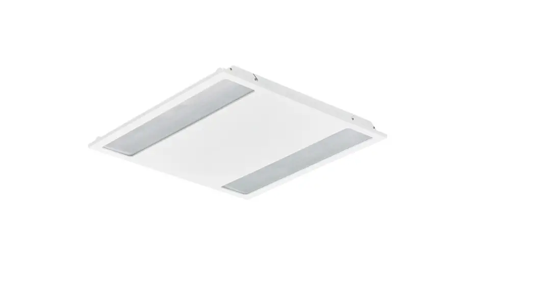
Recessed RC136B
![]()
RC136B LED Panel Coreline
| Power (W) | Lumen output (lm) | Efficacy (lm/(W) | CCT (K) | Class I/II | |||
| RC136B 315_375_435/840 PSD W60L60 OCELB3 RC136B 315_375_435/840 PSD W30L1200CELB3 RC136B 285_345_405/830 PSD W30L120 OC EL | 25W/29W*/ 34W | 3100/370074300 2800/3400*/4000 | 124/126* /126 | 1 4000 | 19 | II | 3.0 |
| 4.5 | |||||||
| 112/117* /118 | 3000 | 4.0 | |||||
| RC136B 315_375_435/840 PSU W60L6ONOCELB3 RC136B 315_375_435/840 PSD W60L6ONOCELB3 | 25W/29W*/ 34W | 3100/3700*/4300 | 141/142* /139 | 4000 | 25 | I | 4.5 |
| II | |||||||
| RC136B 315_375_435/840 PSDW60L600CELB3W3 RC136B 315_375_435/840 PSUW60L600CELB3W | 25W/29W*/ 34W | 3100/3700*/4300 | 127/131* /129 | 4000 | 19 | II | 4.5 |
| I |
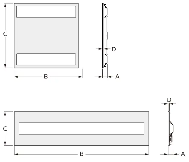
| A(mm) | B(mm) | C(mm) | D(mm) | |
| RC136B W60L60 | 44 | 597 | 597 | 12 |
| RC136B W30L120 | 50 | 1197 | 297 | 12 |
 |  |
 |  |
 | 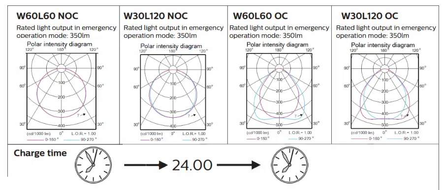 |
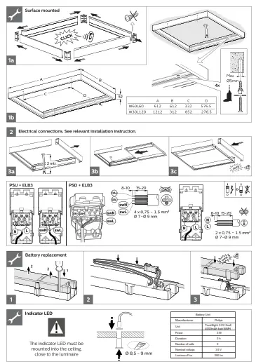
Lifetime
The batteries have a life time expectancy of 4 years when maintained properly. Replace after that time!
Automatic emergency time selection
After installation and power up the driver will detect the battery and start the automatic detection process.
– During automatic detection, the indicator LED willlight up with short green flashes.
– Between minimum 6 and maximum 30 seconds the TrustSight driver will set the battery type (number of cells) and will set the emergency output power accordingly.
After that, the system is defined and fully operational. The battery type definition has influence on the performance during the self-test and on the battery charge method. When the automatic battery detection process is disrupted, e.g. by switching off the permanent mains, the detection process is stopped and the TrustSight emergency driver
will go into emergency mode with the lowest output power. At a next power up, the automatic detection process will start again.
Periodic testing
Periodic tests of emergency lighting luminaires must be performed according to EN50172 clause 7.2.3 and 7.2.4. Switch on in the emergency mode each month by simulation of a failure of the supply to the normal lighting for a period sufficient to ensure that each lamp is illuminated. Twice per year, each luminaire shall be tested for its full rated duration (at least 3hrs).
For more information please consult the TrustSight Gen 3 Design in guide. The latest version is available online.
LED indicator status
| LED indicator (color / flashing) | Error condition | Cause | Solution | ||
| Green / no flashing | System OK, battery fully charged | ||||
| Off | Mains off EM mode, Rest mode, test in progress | ||||
| Green/slow (0.25s on, 1.25s off) | System OK, battery is charging | ||||
| Green / fast (0.25s on, 0.25s off) | System OK, recently tested (c 5 days, Australia mode only) | ||||
| Red/no flashing | Battery voltage too high or too low | No battery connected | Connect battery | ||
| Wrong or bad battery connected | Replace battery | ||||
| Red/fast (0.25s on, 0.25s off) | I Output voltage too low or too high | Wrong LED load connected | Connect right load and perform functional test | ||
| I No load connected or output shorted | Wrong connection | Connect right load and perform functional test | |||
| Red / slow (0.25s on, 1.25s off) | Failed test due to battery | Battery end of life Charger failure | Replace battery and perform duration test. Replace driver | ||
| Red-green / fast Fast flashing: (on-time = 0.25s, off-time = 025s) Slow flashing: (on-time = 0.25s, off-time = 1.25s) | DALI device identification | ||||
| Green /short on-time = 50ms, off-time = 0.95s) | Battery detection | ||||
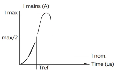
Inrush crrrent
| RC136B PSU | I RC136B PSD | ||
| Electrical characteristics | |||
| [max (A) | 15. | 14. | |
| Tref (us) MCB | 290 No. | 212 | |
| B-10 A | 21 | i 17 | |
| B-13 A B-16 A | 28 35 | 24 30 | |
| B-20 A | 45 | 37 | |
| B-25 A | 56 | 47 | |
| C-10 A C-13 A | 37 48 | 30 40 | |
| C-16 A | 60 | 50 | |
| C-20 A | 76 | 63 | |
| C-25 A | 96 | 80 | |
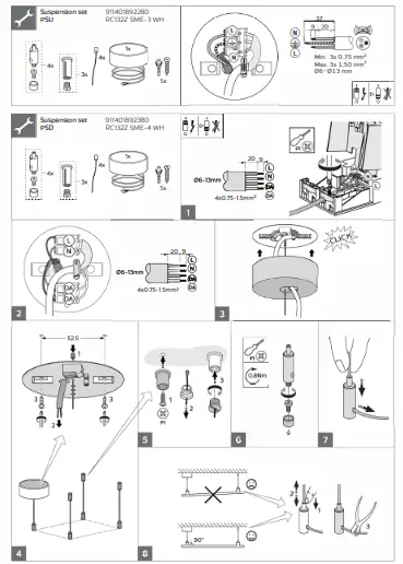
![]() – The luminaire shall be installed by a qualified electrician and wired in accordance with the latest IEE electrical regulations or the national requirements.
– The luminaire shall be installed by a qualified electrician and wired in accordance with the latest IEE electrical regulations or the national requirements.
– The light source contained in this luminaire shall only be replaced by the manufacturer or his service agent or a similar qualified person.
– During installation or maintaining the luminaire please use gloves to avoid spots on the cover.
* To remove dirt and spots use the following:
* Dust: use micro fiber cloths only.
– Fingerprints, etc.: use a cleaner for synthetic materials with antistatic properties. 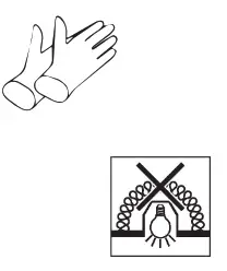
– Luminaires not suitable for covering with thermally insulating material
– Luminaire must not be used or stored in corrosive environment where hazardous materials such as Sulphur,Chlorine, Phthalates, etc, are present.
– Only to be installed outside arm’s reach.
– If the external flexible cable or cord of this luminaire is damaged, it shall be exclusively replaced by the manufacturer or his service agent or a similar qualified person in order to avoid a hazard.
According to new ErP requirement
This product contains a light source of energy efficiency class: see table or label.![]() Disconnect before servicing
Disconnect before servicing
Luminaire has basic insulation between Low Voltage supply and control conductors.
The light source and/or control gear and/or the external flexible cable contained in this luminaire shall only be replaced by the manufacturer or his service agent or a similar qualified person.
Storage, installation, use, operation and maintenance of the products needs to be performed exactly according the instructions in this manual and/or other instructions as
may be provided by us to guarantee safe use of the product over its entire lifetime. Failure to adhere to these instructions will invalidate your entitlement to warranty. Bolts
with indication of torque strength on the drawing need to be tightened using a calibrated torque wrench. Pre-assembled bolts need to be retightened again to the required
torque specification to assure maximum strength over lifetime.
SR compatibility – For SR-based luminaires only SR-Certified components/sensors are to be used
(see also: http://www.lighting.philips.co.uk/oem-emea/products/driving-connected-lighting).
The functional compatibility of two (SR-certified) components/sensors to be used in combination, as well as the override possibility of any line-switch
function used in an SR-based luminaire, is to be released by the master component/sensor supplier. If using a NEMA 7-pin socket on an SR-based luminaire, a full system
verification is required. Not following this advice can/will cause risk of damage and non-compliance for which Signify cannot take any responsibility.
Zhaga-D4i and SR certified compatibility – For Zhaga-D4i/SR-Certified based luminaires only Zhaga-D4i/SR-Certified components/sensors are to be used
(see also: https://Awww.zhagastandard.org/products__/_
https://Avww.lighting.philips.co.uk/oem-emea/products/driving-connected-lighting). The functional
compatibility of two SR-certified and/or Zhaga-D4i controllers/sensors to be used in combination, as well as the override possibility of any line-switch function used in an SR-based/Zhaga-D4i luminaire, is to be released by the master controller/sensor supplier. If using a NEMA 7-pin socket on an SR-based luminaire, a full system verification is required. Not following this advice can/will cause risk of damage and non-compliance for which Signify cannot take any responsibility.
 ©20 2 Signify Holding
All rights reserved. Reproduction in whole or in part is prohibited without the prior written consent of the copyright owner.
The information presented in this document does not form part of any quotation or contract, is believed to be accurate and reliable and may be changed without notice. No liability will be accepted by the publisher for any consequence of its use.
Publication thereof does not convey nor imply any license under patent- or other industrial or intellectual property rights. Signify Holding
The Netherlands


