![]()
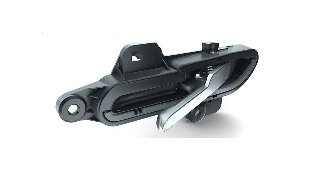
Operational Description and User ManualFLAECH TAGE NFC
General product overview
Function CA:
There are two different capacitive sensors. The first sensor is used for unlock function. This sensor can distinguish an approach and a touch in SW, but there is only a LIN or UART signalization for unlock touch. The second sensor is used for lock function and is designed as a touch sensor. An SW differentiation between lock approach and lock touch is also possible, but just as the unlock sensor there is only a LIN or UART signalization for the locked touch.
Keyless access is enabled by activating the sensors on the door handle in combination withthe door handle-ECU, whereby the vehicle can be unlocked or locked.
Function NFC:
To enable communication with an NFC device, the door handle electronics CA + NFC has a highly integrated transceiver IC for contactless communication at 13,56MHz for automotive applications. This reader has a gateway function, the possibility to buffer required data and various diagnostic information can be provided as well.
The data is transferred to the NFC device according to ISO/IEC 14443-A and the data transmission to the vehicle is realized via LIN-Bus interface. ECP is implemented to communicate with Apple NFC devices.
In LPCD mode the door handle electronics checks the magnetic field for amplitude or phase change. This LPCD polling takes place in adjustable interval lengths.
Environmental conditions
| Operating temperature range: | -40 to +85°C |
| Storage temperature range: | 40 to +105°C |
| Repainting temperature: | 110°C for 1h, 130°C for 0,25h |
| Room temperature: | +23°C ± 5°C |
| Air humidity: | 25% to 90% |
| Test temperature for EOL-Test: | Room temperature |
General manufacturing instructions
- At the beginning of the production process, the serial number is marked on the PCB.
- An unacceptable deflection of the board while placing components must be avoided.
- PCB separation is a particularly critical process. Torsional stress during separation and impact stress during punching shall be avoided.
- The method for depanelling must ensure that no components be damaged. An evidence of the equipment manufacturer is necessary.
- The soldering process should be reflow soldering and selective wave soldering.
- Active cooling of the board after soldering is not permitted.
- The components specifications concerning the temperature gradients must be adhered.
- A reworking of a SMD component with a soldering iron is prohibited.
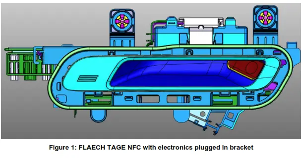
Assembly concept of electronics FLAECH TAGE NFC
NFC antenna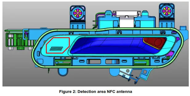
Connector definitions
Connector BMW I20 CA + NFC,FLAECH TAGE NFC
The BMW I20 CA and CA + NFC electronic module have the following connector pins:
| Pin 1 (yellow) | = LIN |
| Pin 2 | = n.c. |
| Pin 3 (brown) | = clamp 31 (GND) |
| Pin 4 (red) | = clamp 30 (+Ubat) |
The BMW I20 electrical opening module has the following connector pins:
| Pin 1 (black) | = micro switch |
| Pin 2 (black) | = clamp 31 (GND) |
| Pin 3 (brown) | = clamp 31 (GND) |
| Pin 4 (red) | = clamp 30 (+Ubat) |
The BMW I20 light module has the following connector pins:
| Pin 1 (red) | = positive supply light module |
| Pin 2 (white) | = clamp 31 (GND) |
Electrical Characteristics
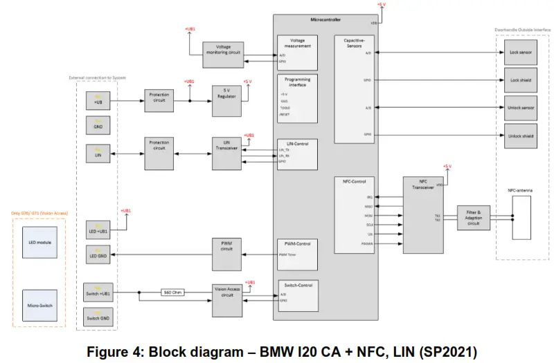
Block diagram – BMW I20 CA + NFC, LIN
Operating voltages
| Operating voltage range: | +Ubat = 9V to 16V DC |
| LIN operating voltage range: | +Ubat = 8V to 18V DC |
| Test voltage for EOL: | +Ubat = 12V ± 2% DC |
Current consumption
| – Series parts current consumption: o Quiescent current: | Iquies ≤ 400µA for 4 TAGE per vehicle Iquies ≤ 200µA for 2 TAGE per vehicle CA = 65µA CA + NFC = 150µA Iactive ≤ 250mA CA < 10mA CA + NFC < 120mA |
The final values have to be defined with series parts by Huf-HQ.
Timing conditions
- Polling rate:
| o CA o CA + NFC • NFC-LPCD pulse: • Clock rate microcontroller: o Kapaburst (333kHz/ 400kHz) o A/D conversion + data handling • Baudrate: o UART o LIN | 20ms 20ms (Kapa), 100ms (NFC) 40µs 4MHz 32MHz 4800Bit/s up to 38400Bit/s 9600Bit/s up to 38400Bit/s |
Regulatory Information
FEDERAL COMMUNICATIONS COMMISSION INTERFERENCE STATEMENT
This equipment has been tested and found to comply with the limits for a Class B digital device, pursuant to part 15 of the FCC Rules. These limits are designed to provide reasonable protection against harmful interference in a residential installation. This equipment generates, uses, and can radiate radio frequency energy and, if not installed and used in accordance with the instructions, may cause harmful interference to radio communications. However, there is no guarantee that interference will not occur in a particular installation. If this equipment does cause harmful interference to radio or television reception, which can be determined by turning the equipment off and on, the user is encouraged to try to correct the interference by one or more of the following measures:
- Reorient or relocate the receiving antenna.
- Increase the separation between the equipment and receiver.
- Connect the equipment into an outlet on a circuit different from that to which the receiver is connected.
- Consult the dealer or an experienced radio/ TV technician for help.
CAUTION:
Any changes or modifications not expressly approved by the grantee of this device could void the user’s authority to operate the equipment
Canada, Innovation, Science and Economic Development Canada (ISED)
Notices
This device contains license-exempt transmitter(s)/receiver(s) that comply with Innovation, Science, and Economic Development Canada’s license-exempt RSS(s). Operation is subject to the following two conditions:
- This device may not cause interference.
- This device must accept any interference, including interference that may cause undesired operation of the device.


