Qubino ZMNHX 3-Phase Smart Meter Instruction Manual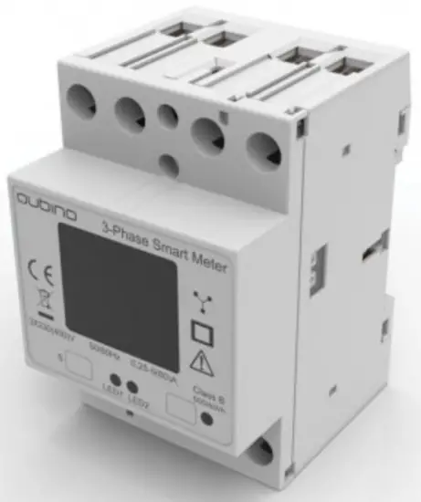
Introduction
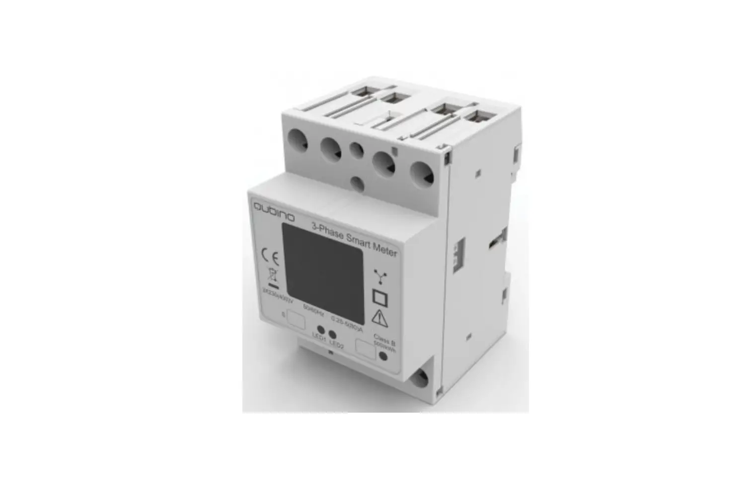
Qubino 3-Phase Smart Meter is used for energy measurements in three phase electrical power network and can be used in residential, industrial and utility applications. The device measures energy directly in 4-wire networks according to the principle of fast sampling of voltage and current signals. It is designed to be mounted on DIN rail.
PACKAGE CONTENTS
3-Phase Smart Meter Device, Installation Manual, Z-Wave DKS label
INSTALLATION
To prevent electrical shock and/or equipment damage, disconnect electrical power at the main fuse or circuit breaker (if it is compliant to standard IEC947- before installation and maintenance.
Be aware that even if the circuit breaker is off, some voltage may remain in the wires — before proceeding with the installation, make sure no voltage is present in the wiring.
Take extra precautions to avoid accidentally turning on the device during installation.
Connect the device exactly according to the diagram.
Mount the device on the DIN rail.
Danger of electrocution!
Installation of this device requires a great degree of skill and may only be performed by a licensed and qualified electrician. Please keep in mind that even when the device is turned off, some voltage may still be present in the device terminals.
Note!
Do not connect the device to loads exceeding the recommended values. Connect the device exactly as shown in the provided diagrams. Improper wiring may be dangerous and result in equipment damage.
Electrical installation must be protected by over current protection with rated breaking capacity up to 65A and must be used according to the wiring diagram to achieve the appropriate overload protection of the device.
Z-WAVE INCLUSION (Adding to Z-wave network)
AUTO-INCLUSION
- Enable inclusion mode on your Z-Wave gateway (hub)
- Connect the device to the power supply
- Auto-inclusion will be initiated within 10 seconds after connection to the power supply and the device will automatically enroll in your network
MANUAL INCLUSION
- Connect the device to the power supply
- Enable inclusion mode on gateway (hub) and press and hold the S (Service) button between 0,5 and less than 6s.
- A new device will appear on your dashboard
Note: In case of S2 Security inclusion a dialog will appear prompting you to enter the corresponding PIN number (5 underlined digits) that are written on the module label and the label inserted in the packaging (check the example picture).
Z-WAVE DSK
24659
57239
43917
56135
13740
22935
64301
14435
PIN:24659
IMPORTANT: The PIN code must not be lost
Z-WAVE EXCLUSION/RESET (Removing from Z-Wave network)
Z-WAVE EXCLUSION
- Connect the device to the power supply
- Enable exclusion mode on your Z-Wave gateway (hub), press and hold S
(Service) button between 0,5 and less than 6 seconds. - The device will be excluded from your network but none of the custom configuration parameters will be erased.
FACTORY RESET
- Connect the device to the power supply
- Press S (Service) button for at least 6 to 20 seconds.
By resetting the device, all custom parameters previously set on the device
will return to their default values, and the owner`s ID will be deleted. Use this
reset procedure only when the main gateway (hub) is missing or otherwise inoperable.
IMPORTANT DISCLAIMER
Z-Wave wireless communication is not always 100% reliable. This device should not be used in situations in which life and/or valuables are solely dependent on its functioning. If the device is not recognized by your gateway (hub) or shows up incorrectly, you may need to change the device type manually and make sure your gateway (hub) supports multi-channel devices.
Contact us for help before returning the product:
http://qubino.com/support/#email
WARNING
Do not dispose of electrical appliances as unsorted municipal waste, use separate collection facilities. Contact your local government for information regarding the collection systems available. If electrical appliances are disposed of in landfills or dumps, hazardous substances can leak into the groundwater and get into the food chain, damaging your health and wellbeing. When replacing old appliances with new ones, the retailer is legally obligated to take back your old appliance for disposal free of charge.
ELECTRICAL DIAGRAM
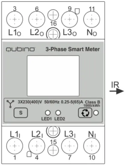
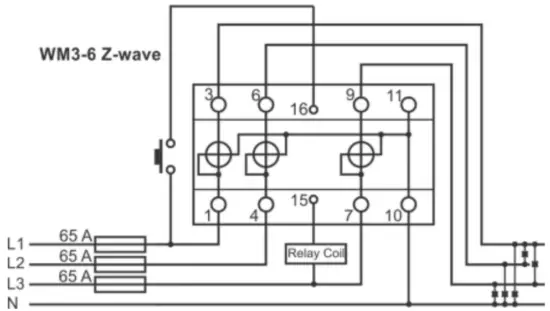
Note: Neutral wire has to be connected to the Smart Meter.
L1I, L2I, L3I Live input
Ni Neutral input
L1O,L2O, L3O Live output
No Neutral output
16 Input for IR external relay/Ext. relay
15 Output for External relay (max. 3W)
S Service button (used to add or remove device from
the Z-Wave network)
LED1 Green – Power on (solid) / no ID (blinking slow 1s) /
Inc./Exc. mode (blinking fast 0,5s)
LED2 Yellow on – output on (any) / Yellow off – outputs off (both) / Blinking IR communication error
IR Output for IR external relay (BICOM)
1000imp/kWh Red – Pulse rate (On – no load indication)
Display Check the explanation in the extended manual
MEASUREMENTS
| Phase voltage U1,U2,U3 | [V] |
| Phase current I1,I2,I3 | [A] |
| Power – Active, per phase and total | [W] |
| Power – Reactive total | [kvar] |
| Energy –Active Import/export | [kWh] |
| Energy – Reactive total | [kvarh] |
| Energy – Apparent | [kVAh] |
| Power Factor | PF |
EXTERNAL RELAYS
It is possible to connect two external relays to the Smart Meter device.
One controlled by built-in optical (IR) communication port on the side, the other controlled by output on terminal 15.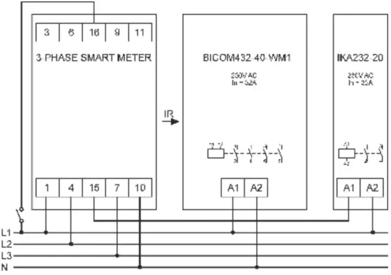
TECHNICAL SPECIFICATIONS
| Main terminals | |
| Contacts capacity | |
| Rigid/ (flexible) | 2.5 … 25 (16) mm2 |
| Connection screws Vis | M5 |
| Max torque | 3.5 Nm (PZ2) |
| Optional terminals | |
| Contact capacity | 1… 2.5 mm2 |
| Screws | M3 |
| Max torque | 1.2 Nm |
| Measuring input | |
| Type (connection) | three phase (4u) |
| Basic current (Ib) | 5 A |
| Maximum current (Imax) | 65 A |
| Minimum current (Imin) | 0.25 A |
| Transitional current (Itr) | 0.5 A |
| Starting current | 20 mA |
| Nominal voltage (Un) | 230V (+15-20%) |
| Power consumption per phase at Un | < 8 VA |
| Nominal frequency | 50 and 60 Hz |
| Accuracy | |
| Active energy | class 1 EN 62053-21, class B EN 50470-3 ±1.5% from Imin to Itr ±1% from Itr to Imax |
| Reactive energy | class 2 EN 62053-23 ±2.5% from Imin to Itr ±2% from Itr to Imax |
| Voltage | ±1% of measured value |
| Current | ±1% of Iref from Ist to Iref |
| Active Power | ±1% of nominal power (Un*Iref) from Ist to Iref |
| Reactive, Apparent power | ±2% of nominal power from Ist to Iref |
| Frequency | ±0.5% of measured value |
| LED: | |
| Colour | Red |
| Pulse rate | 1000 imp/kWh |
| Led on | no load indication |
| Optical communication | |
| Type | IR – used to control BICOM432-40-IR |
| Digital Input (16) | |
| Rated voltage | 230 V (+15 -20%) |
| Digital Output (15) | |
| Rated voltage | 230 V (+15 -20%) |
| Maximum load current | 50 mA |
| LCD | Display 7+1 digit (100Wh resolution) |
| Safety | |
| Indoor Meter | Yes |
| Degree of pollution | 2 |
| Protection class | II |
| Standard | IEC 62052-31 |
| Safety and ambient conditions | |
| According standards for indoor active energy Meters. | |
| Temperature and climatic condition according to EN 62052 11.. | |
| Temperatur- 62052 11. | |
| Dust/water protection | IP50 (For IP51 it should be installed in an appropriate cabinet) |
| Operating temperature | -25 … 55°C |
| Storage temperature | -40 … 70°C |
| Humidity | Non-condensing |
| Enclosure material | self-extinguish, complying UL94 V |
| Indoor Meter | yes |
| Degree of pollution | 2 |
| Protection Class | II |
| Standard | IEC 62052-31 |
| Mechanical environment | M1 |
| Electromagnetic environment | E2 |
| RF communication distance
| up to 30 m indoors (depending on building materials)
|
| Weight (with packaging) | 220g (240g) |
| Operating frequency band(s)/
| Z-Wave (868,4Mhz EU;865,2MHz;869,0MHz; 921,4MHz;908,4 MHz; 916MHz;919,8MHz; 922,5MHz;919,7-921,7- 923,7MHz;868,1MHz;920,9 MHz |
| Maximum radio-frequency power transmitted in frequency
| <2,5mW |
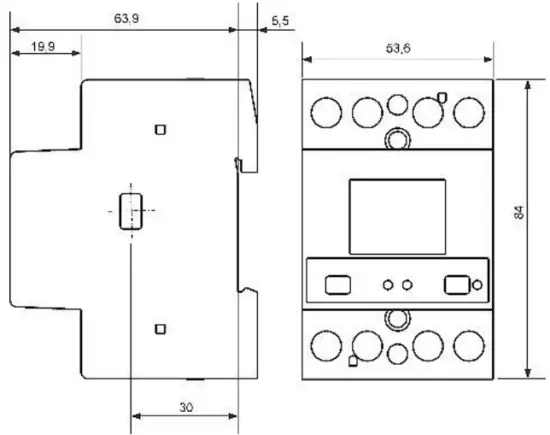
| Installation | DIN rail 35mm (EN 60715) |
| Dimensions (W x H x D) | 53.6 x 84 x 69.4mm |
| Package dimensions (W x H x D)
| 58 x 84 x 95mm |
| Colour | RAL 7035 |
- Depends on ordering code
EU Directives conformity:
EU Directive on EMC 2014/30/EU; EU Directive on Low Voltage 2014/35/EU;
EC Directive; WEEE 2002/96/EC; EU RED Directive 2014/53/EU
Dimensional drawings
Warning: The case is sealed. No warranty if the case is opened.
ORDERING CODE AND FREQUENCIES
ZMNHXXY – X, Y values define product version per region. Please check online the extended manual or catalogue for the right version.
Download the extended manual: scan the QR code below or visit:
http://qubino.com/products/
![]()
SIMPLIFIED EU DECLARATION OF CONFORMITY
Hereby, Goap d.o.o. Nova Gorica declares that the radio equipment type 3- phase Smart meter is in compliance with Directive 2014/53/EU. The full text of the EU declaration of conformity is available at the following internet address: https://qubino.com/products/3-phase-smart-meter/
GOAP d.o.o. Nova Gorica
Ulica Klementa Juga 007, 5250 Solkan, Slovenia
E-mail: [email protected]; Tel: +386 5 335 95 00
Web: www.qubino.com; Date: 12.01.2022; V 4.3