![]() WayPoint30A Series AC Outdoor Power Supplies
WayPoint30A Series AC Outdoor Power Supplies
Installation Guide
Models Include:
| WayPoint30AU – 24VAC @ 12.5A and/or 28VAC @ 10A. – Two (2) fuse-protected outputs. WayPoint30A4U – 24VAC @ 12.5A and/or 28VAC @ 10A. – Four (4) fuse-protected outputs. WayPoint30A8U – 24VAC @ 12.5A and/or 28VAC @ 10A. – Eight (8) fuse-protected outputs. | WayPoint30ADU – 24VAC @ 12.5A and/or 28VAC @ 10A. – Two (2) Class 2 Rated PTC-protected power-limited outputs. WayPoint30A4DU – 24VAC @ 12.5A and/or 28VAC @ 10A. – Four (4) Class 2 Rated PTC-protected power-limited outputs. WayPoint30A8DU – 24VAC @ 12.5A and/or 28VAC @ 10A. – Eight (8) Class 2 Rated PTC-protected power-limited outputs. |

Installing Company: ____________ Service Rep. Name: ________________
Address: _____________________ Phone #: ______
Overview:
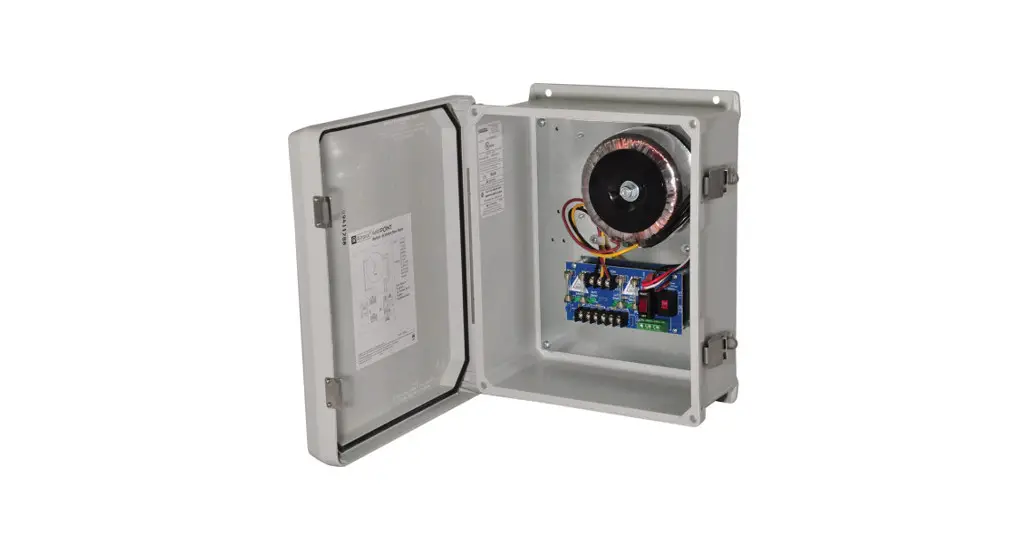
Altronix WayPoint Outdoor Power Supplies provide 24VAC and/or 28VAC distributed via two (2), four (4) or eight (8) outputs for powering CCTV cameras, heaters, and other video accessories.
WayPoint30A Series AC Reference Chart:
| Altronix Model Number | Output Voltage | Total Output Current (Power) | Number & Type of Outputs | Fuse Output Ratings | PTC Output Ratings | Class 2 Rated power-limited outputs | Input Current Draw | Product Weight | |
| 115VAC 60Hz | 230VAC 50Hz | ||||||||
| WayPoint30AU | 24VAC | 12.5A | 1 | 10A/ 32V | 3.0A | 1.5A | 4.68kg | ||
| 28VAC | 10A | ||||||||
| 24VAC and 28VAC | 10A | 1 of each | |||||||
| WayPoint3OADU | 24VAC | 12.5A | 1 | — | 9A | 4.68kg | |||
| 28VAC | 10A | ||||||||
| 24VAC and 28VAC | 10A | 1 of each | |||||||
| WayPoint30A4U | 24VAC | 12.5A | 4 Fused | 10N 32V | 4.68kg | ||||
| 28VAC | 10A | ||||||||
| WayPoint30A4DU | 24VAC | 12.5A | 4 PTCs | — | 2.5A | ✓ | 4.68kg | ||
| 28VAC | 10A | ||||||||
| WayPoint30A8U | 24VAC | 12.5A | 8 Fused | 5A/ 32V | 4.8kg | ||||
| 28VAC | 10A | ||||||||
| WayPoint30A8DU | 24VAC | 12.5A | 8 PTCs | — | 2.5A | ✓ | 4.8kg | ||
| 28VAC | 10A | ||||||||
Specifications
Agency Listings:
- UL/cUL Listed:
UL 60950-1 Information Technology Equipment.
UL 60950-22 Equipment to be Installed Outdoors. - CE European Conformity.
Input:
- Input: 115VAC, 60Hz, 3A or 230VAC, 50Hz, 1.5A.
Output:
- Output options:
a. 24VAC or 28VAC.
b. Both 24VAC and 28VAC
(WayPoint30AU/ADU only). - Fuse ratings:
WayPoint30AU and WayPoint30A4U: 10A
WayPoint30A8U: 5A.
Visual Indicators:
- Individual power output LED indicators.
- Illuminated master power switch.
Features:
- Surge suppression.
- Spare fuses included.
Accessories:
- Optional PMK1 Pole Mount Kit simplifies installation of outdoor units.
Enclosure:
- NEMA 4/4X, IP66-11 Rated enclosure for outdoor use.
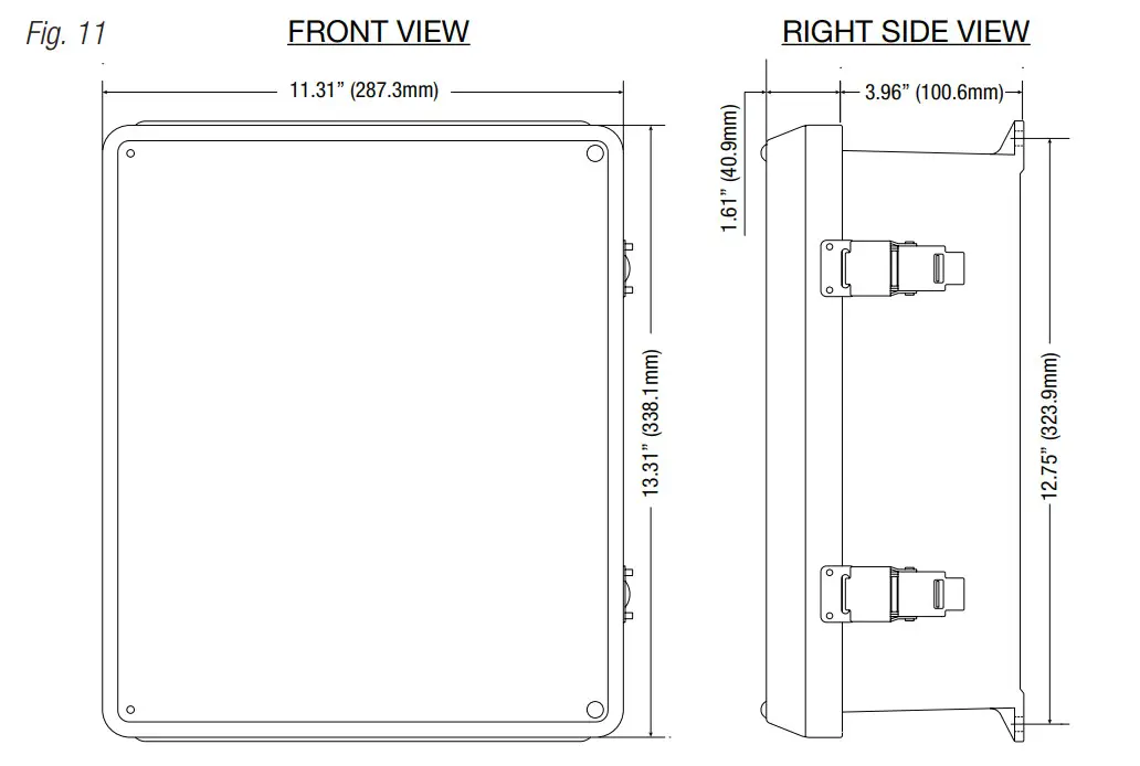
- Enclosure Dimensions (H x W x D approx.): 13.31” x 11.31” x 5.59” (338.1 mm x 287.3 mm x 142 mm).
Installation Instructions
Unit shall be installed in accordance with The National Electrical Code and all applicable Local Regulations.
- Remove the backplane from the enclosure prior to mounting (do not discard hardware).
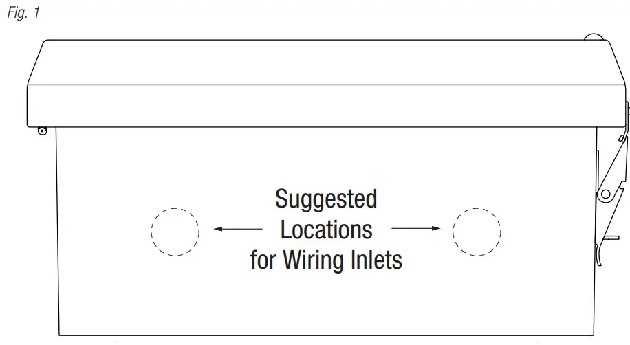
- Mark and drill desired inlets on the enclosure to facilitate wiring (Fig. 1, 4).
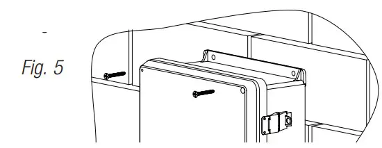
- Mount unit in the desired location. Mark and drill holes to line up with the top and bottom holes of the enclosure flange. Secure the enclosure with appropriate fasteners (Fig. 5, pg. 8 and Fig. 11, 12).
- Mount the backplane to the enclosure with hardware.
- Set the input voltage selector switch for 115VAC or 230VAC operation (Figs. 2-4, 5-7)
- To facilitate wire entry utilize weather-tight NEMA 4-rated connectors, bushings, and cable.
- Set the illuminated master power disconnect circuit breaker to the [OFF] position (Figs. 2-4, pgs. 5-7).
- Connect unswitched AC power (115VAC/230VAC 50/60 Hz) to terminals marked [L, N] (Figs. 2-4, pgs. 4-6). Green branch wire connects to earth (safety) ground lug C)
The wire gauge range of connectors is 14 AWG to 11 AWG (1.6 mm to 2.5 mm diameter). - Set the illuminated master power disconnect circuit breaker to the (RESET/ON) position (Figs. 2-4, pgs.
- WayPoint30A4U/A4DU and WayPoint30A8U/A8DU are factory set for 24VAC operation. For 28VAC operation adjust unit prior to mounting and applying power as follows: Change The wire position so that the black wire [28V] is connected to the terminal marked [P] and the yellow wire [24V] is connected to the terminal marked [S].
- Measure output voltage on terminals marked [COM, 24V, 28V] on WayPoint30AU or WayPoint3OADU (Fig. 2, pg. 5) or [1-4] or [1-8 COM] on WayPoint30A4U, WayPoint30A4DU, WayPoint30A8U and WayPoint30A8DU before connecting devices (Fig. 3, pg. 6, Fig. 4, 7).
This helps avoid potential damage. - Set the illuminated master power disconnect circuit breaker to the [OFF] position (Figs. 2-4, 5-7).
- Connecting devices to WayPoint30AU or WayPoint3OADU:
For 24VAC output connect devices to terminals marked [COM, 24V] (Fig. 2, pg. 5).
For 28VAC output connect devices to terminals marked [COM, 28V] (Fig. 2, pg. 5).
Connecting devices to WayPoint30A4U or WayPoint30A4DU: Connect the device to terminals marked [1-4] and [COM] (Fig. 3, pg. 6).
Connecting devices to WayPoint30A8U or WayPoint30A8DU: Connect the device to terminals marked [1-8] and [COM] (Fig. 4, pg. 7). - Set the illuminated master power disconnect circuit breaker to the [RESET/ON] position (Figs. 2-4, pgs.
- LEDs will illuminate indicating each output is powered (Figs. 2-4, pgs. 5-7).
- Upon completion of wiring secure the enclosure door with latches and optional
Caution: Equipment to be installed/serviced by authorized/trained personnel only. Shut branch circuit power before installing/servicing equipment.
WARNING: When installing in a non-restricted service area use lock or other fastener means on door latches. This installation should be made by qualified service personnel and should conform to all local codes and in accordance with the National Electrical Code.
Bottom of Enclosure
LED Identification Chart:
| ON | OFF |
| Normal operating condition. | No AC output. Blown fuse or tripped PTC, illuminated master power disconnect circuit breaker is tripped or OFF, AC failure. |
To reset a tripped PTC turn the power off for 1 minute and then turn it back on.
Technical Specifications:
| Parameter | Description |
| Input power requirements | 115VAC, 60Hz, 3A or 230VAC, 50Hz, 1.5A. |
| Indicators | Individual power output LED indicators. Illuminated master power switch. |
| Environmental Conditions | Operating Ambient Temperature: For 24VAC 0 12.5A output: – 40°C to 60°C (- 40°F to 140°F). For 28VAC 0 10.0A output: – 40°C to 70°C (- 40°F to 158°F). Relative Humidity: 85%, +/- 5% Storage Temperature: – 40°C to 75°C (- 40°F to 167°F). Operating Altitude: – 304.8 to 2,000m. |
| Regulatory Compliance | UL/cUL Listed for Information Technology Equipment (UL 60950-1) Equipment to be Installed Outdoors (UL 60950-22). CE European Conformity. |
For fuse-protected models:
Replace blade-type fuses with ratings from 3A up to 10A.
WayPoint30AU and WayPoint30A4U incorporate 10A fuses. WayPoint30A8U incorporates 5A fuses.
Fig. 2 – WayPoint30AU (Fuses)
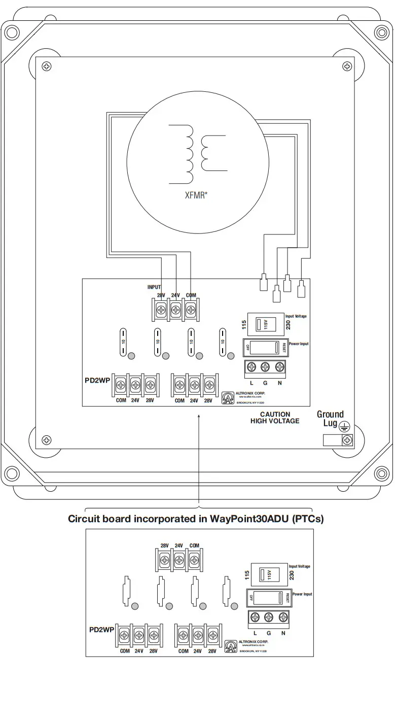
Fig. 3 – WayPoint30A4U (Fuses)
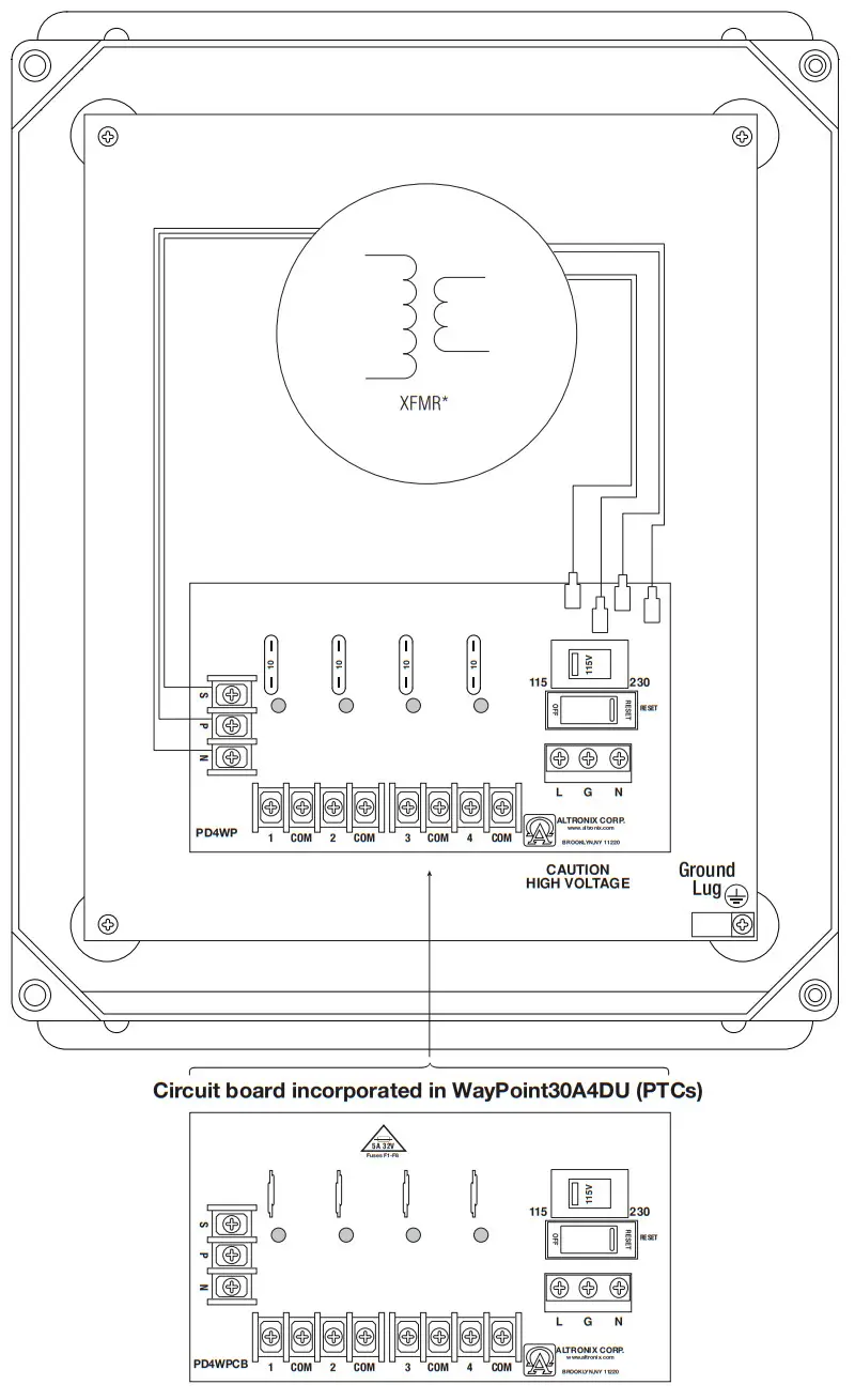
Fig. 4 – WayPoint30A8U (Fuses)
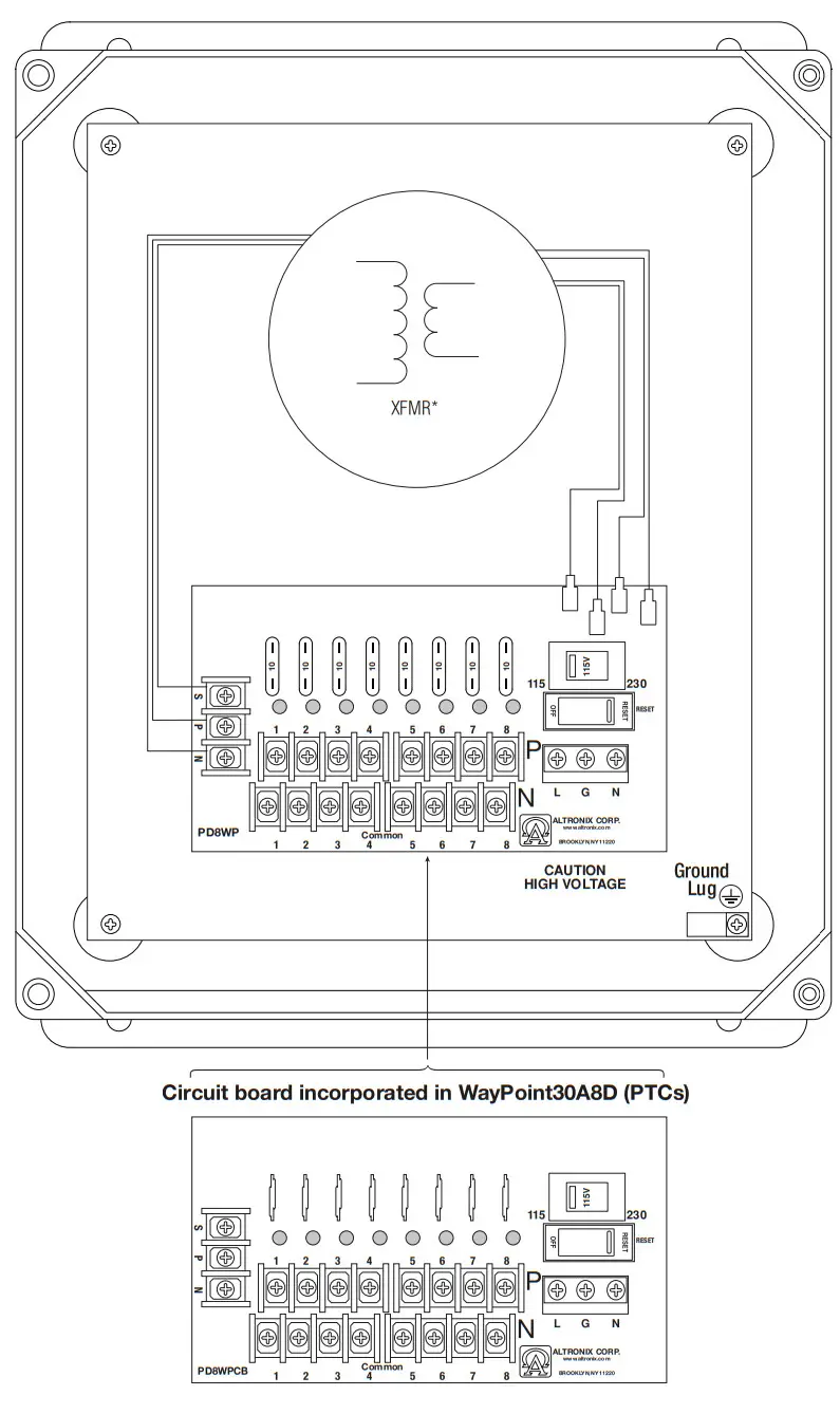
Wall Mount Installation:
- Place the unit at the desired location and secure it with mounting screws (not included) (Fig. 5, pg. 8).
Pole Mounting Using Optional Pole Mount Kit PMK1:
This installation should be made by qualified service personnel. This product contains no serviceable parts.
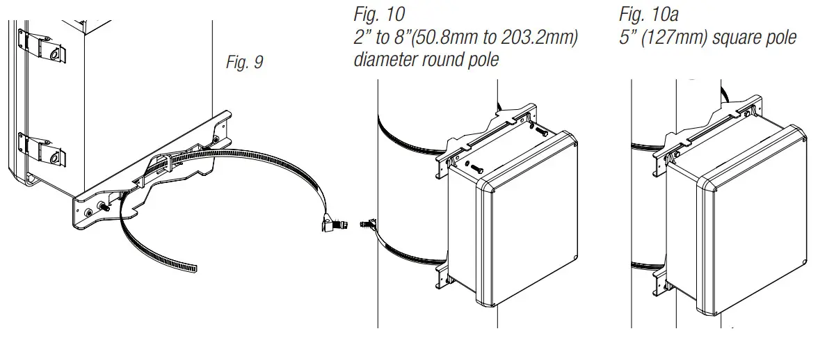
PMK1 outdoor pole mount kit is designed to simplify the installation of Altronix outdoor-rated power supplies and accessories housed in models WP1, WP3 and WP4 NEMA-rated enclosures. PMK1 can be mounted on 2” to 8” (50.8mm to 203.2mm) diameter round or 5” (127mm) square poles. Brackets are designed for use with the Wormgear Quick Release Straps (two included).
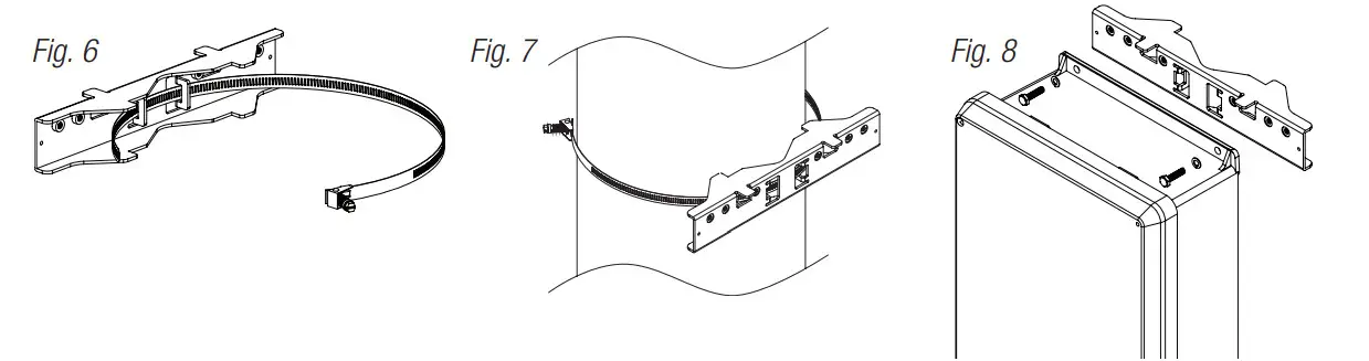
- Thread one (1) wormgear quick-release strap through the slots on the back of a mounting bracket (Fig. 6, pg. 8).
- Once the desired height of the top Pole Mount bracket is achieved, tighten the straps down by sliding the open the end of the strap through the locking mechanism on the strap, then tighten the screw with flat head screwdriver or 5/16” hex socket driver (Fig. 7, pg. 8 and Fig. 9, pg. 8).

- Attach the bottom bracket to the enclosure by inserting bolts through the flange of the enclosure and into the bracket, tightening bolts with a 7/16” hex socket (Fig. 8, pg. 8).
- Thread the second wormgear quick-release strap through the slots on the back of the bottom mounting bracket (Fig. 9, pg. 8).
- Mount the enclosure onto the top bracket by inserting bolts through the flange of the enclosure and into the bracket, tightening bolts with a 7/16” hex socket (Fig. 7, pg. 8).
- Tighten the straps of the bottom bracket down by sliding the open end of the strap through the locking mechanism on the strap, then tighten the screw with flat head screwdriver or 5/16” hex socket driver (Fig. 7, pg. 8).
- Clip excess straps.
![]() The lightning flash with an arrowhead symbol within an equilateral triangle is intended to alert the user to the presence of an insulated DANGEROUS VOLTAGE within the product’s enclosure that may be of sufficient magnitude to constitute an electric shock.
The lightning flash with an arrowhead symbol within an equilateral triangle is intended to alert the user to the presence of an insulated DANGEROUS VOLTAGE within the product’s enclosure that may be of sufficient magnitude to constitute an electric shock.![]() The exclamation point within an equilateral triangle is intended to alert the user to the presence of important operating and maintenance (servicing) instructions in the literature accompanying the appliance.
The exclamation point within an equilateral triangle is intended to alert the user to the presence of important operating and maintenance (servicing) instructions in the literature accompanying the appliance.
| CAUTION RISK OF ELECTRIC SHOK DO NOT OPEN |
CAUTION: To reduce the risk of electric shock do not open the enclosure.
There are no user-serviceable parts inside.
Refer servicing to qualified service personnel.
Enclosure Dimensions
(H x W x D approximate):
13.31” x 11.31” x 5.59” (338.1mm x 287.3mm x 142mm)
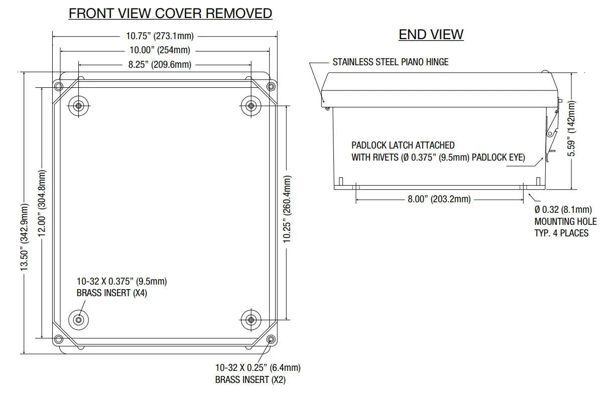
THE FRONT VIEW COVER REMOVED
Altronix is not responsible for any typographical errors.
140 58th Street, Brooklyn, New York 11220 USA | phone: 718-567-8181 | fax: 718-567-9056
website: www.altronix.com | e-mail: [email protected] | Lifetime Warranty
IIWayPoint30A Series
I10U


