OLEI LR-16F 3D LiDAR Sensor Communication Data Protocol
Please read this manual before using the product for the best product performance.
Be sure to keep this manual for future reference.
Type of Connector
- Connector: RJ-45 standard internet connector
- Basic protocol: UDP/IP standard internet protocol, Data are in little-endian format, lower byte first
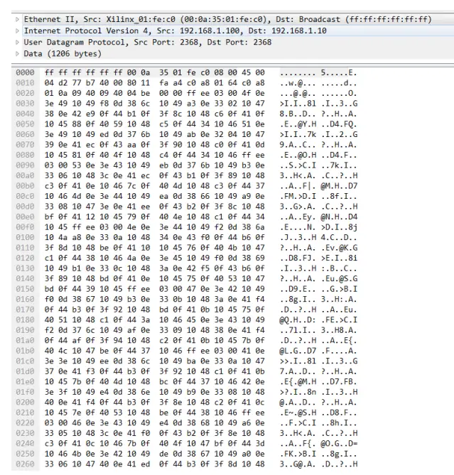
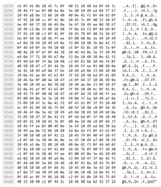
Data Packet Format
Overview
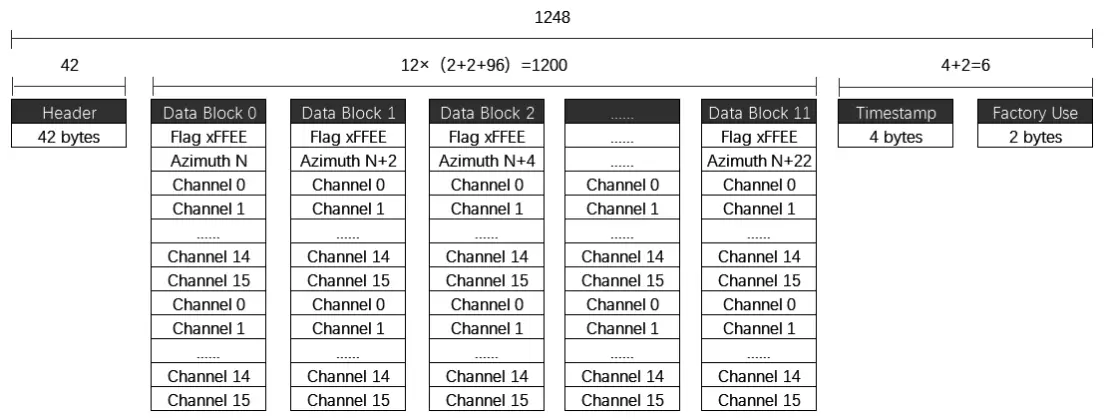
The total length of a data frame is 1248 bytes, including:
- Frame header: 42 bytes
- Data block: 12X(2+2+96) = 1,200 bytes
- Time stamp: 4 Bytes
- Factory mark: 2 Bytes
Header
| Offset | Length | Description |
|
0 |
14 | Ethernet II include: Destination MAC:(6 Byte) Sourse MAC:(6 Byte) Type: (2 Byte) |
|
14 |
20 | Internet Protocol include: Version & Header Length :(1 Byte) Differentiated Services Field: (1 Byte) Total Length:(2 Byte) Identification: (2 Byte) Flags: (1 Byte) Fragment Offse: (1 Byte) Time to Live: (1 Byte) Protocol: (1 Byte) Header Checksum: (2 Byte) |
| Destination IP: (4 Byte) Sourse IP: (4 Byte) | ||
|
34 |
8 | User Datagram Protocol include: Sourse Port:(2 Byte) Destination Port: (2 Byte) Data Length:(2 Byte) Checksum: (2 Byte) |
Data block definition
The laser returned data consists of 12 data blocks. Each data block starts with a 2-byte identifier 0xFFEE, followed by a 2-byte azimuth angle and a total of 32 data points. The lase returned value of each channel contains a 2-byte distance value and a 1-byte calibration reflectivity value.
| Offset | Length | Description |
| 0 | 2 | Flag, it is always 0xFFEE |
| 2 | 2 | Angle Data |
| 4 | 2 | Ch0 Ranging Data |
| 6 | 1 | Ch0 Reflectivity Data |
| 7 | 2 | Ch1 Ranging Data |
| 9 | 1 | Ch1 Reflectivity Data |
| 10 | 2 | Ch2 Ranging Data |
| 12 | 1 | Ch2 Reflectivity Data |
| – | – | – |
| 49 | 2 | Ch0 Ranging Data |
| 51 | 1 | Ch15 Reflectivity Data |
| 52 | 2 | Ch0 Ranging Data |
| 54 | 1 | Ch0 Reflectivity Data |
| 55 | 2 | Ch1 Ranging Data |
| 57 | 1 | Ch1 Reflectivity Data |
| 58 | 2 | Ch2 Ranging Data |
| 60 | 1 | Ch2 Reflectivity Data |
| – | – | – |
| 97 | 2 | Ch15 Ranging Data |
| 99 | 1 | Ch15 Reflectivity Data |
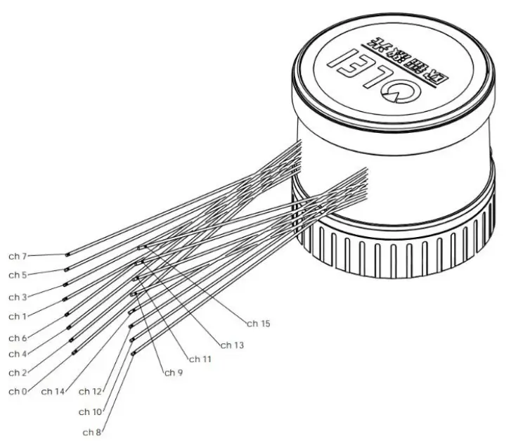
The vertical angle is defined as following:
| Laser ID | Vertical Angle |
| 0 | -15° |
| 1 | 1° |
| 2 | -13° |
| 3 | 3° |
| 4 | -11° |
| 5 | 5° |
| 6 | -9° |
| 7 | 7° |
| 8 | -7° |
| 9 | 9° |
| 10 | -5° |
| 11 | 11° |
| 12 | -3° |
| 13 | 13° |
| 14 | -1° |
| 15 | 15° |
Time stamp
| Offset | Length | Description |
| 0 | 4 | Timestamp [31:0]: [31:20] count of Seconds [19:0] count of Microsecond |
Factory mark
| Offset | Length | Description |
| 0 | 2 | Factory:(2 Byte)0x00,0x10 |
Example
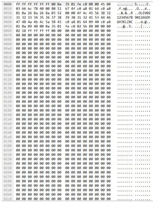
Communication protocol-information package
Overview
| Header | Lidar Info | GPS Info |
| 42 Bytes | 768Bytes | 74 Bytes |
Length of data package: 884 Bytes
Note: The port number of the information package cannot be changed, the local and target ports are both 9866
Definition of header
| Offset | Length | Description |
|
0 |
14 | Ethernet II Include: Destination MAC:(6 Byte) Sourse MAC:(6 Byte) Type: (2 Byte) |
|
14 |
20 | Internet Protocol Include: Version & Header Length :(1 Byte) Differentiated Services Field: (1 Byte) Total Length:(2 Byte) Identification: (2 Byte) |
| Flags: (1 Byte) Fragment Offse: (1 Byte) Time to Live: (1 Byte) Protocol: (1 Byte) Header Checksum: (2 Byte) Destination IP: (4 Byte) Sourse IP: (4 Byte) | ||
|
34 |
8 | User Datagram Protocol Include: Sourse Port:(2 Byte) Destination Port: (2 Byte) Data Length:(2 Byte) Checksum: (2 Byte) |
Definition of Lidar Info
| Offset | Length | Description |
| 0 | 6 | Factory Code |
| 6 | 12 | Model Number |
| 18 | 12 | Series Number |
| 30 | 4 | Sourse IP |
| 34 | 2 | Sourse data Port |
| 36 | 4 | Destination IP |
| 40 | 2 | Destination data Port |
| 42 | 6 | Source MAC |
| 48 | 2 | Motor Speed |
| 50 | 1 | [7] GPS Connection, 0: Connected, 1: No connection [6] Top circuit error flag 0: Normal, 1: Error [5:0] Reserve |
|
51 |
1 | GPS Enable & Baud rate 0x00:GPS GPS Power Off 0x01:GPS Power On, Baud rate 4800 0x02:GPS Power On, Baud rate 9600 0x03:GPS Power On, Baud rate 115200 |
| 52 | 1 | Reserve |
| 53 | 1 | Reserve |
| 54 | 2 | Top circuit Temperature, DataX0.0625℃ |
| 56 | 2 | Bottom circuit Temperature, DataX0.0625℃ |
| 58 | 2 | Reserve |
| 60 | 32 | CH0-CH15 Channel static offset |
| 92 | 4 | Reserve |
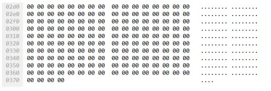
| 96 | 672 | Reserve |
| 768 | 74 | GPS Information |
Example
Setup the protocol
Follow the UDP protocol, user setup protocol, upper computer sends 8 bytes
| Name | Address | Data |
| Number of bytes | 2 Bytes | 6 Bytes |
| Address | Name | Byte Definition [31:0] | |
| F000 | Local IP | [47:16]=local_ip,[15:0] =local_port | |
| F001 | Remote IP | [31:0]=remote_ip,[15:0]= remote_port | |
|
F002 |
Speed, GPS enable, baud rate | [47:32] =rom_speed_ctrl [31:24]=GPS_en 0x00 = off 0x01 = enabled and the baud rate is 4800 0x02= enabled and the baud rate is 9600 0x03 = enabled and 115200 baud rate [23:0]Reserved | |
| Example: | |||
| Local ip and port | F0 00 C0 A8 01 64 09 40 | 192.168.1.100 2368 | |
| Target ip and port | F0 01 C0 A8 01 0A 09 40 | 192.168.1.10 2368 | |
| Rotating speed | F0 02 02 58 00 00 00 00 | speed 600 | |
Example:
- Local ip and port F0 00 C0 A8 01 64 09 40 192.168.1.100 2368
- Target ip and port F0 01 C0 A8 01 0A 09 40 192.168.1.10 2368
- Rotating speed F0 02 02 58 00 00 00 00 speed 600
- Restart the 3D LiDAR each time the modification is completed.
- Optional rotating speed: 300 or 600. optional baud rate:4800/9600/115200 .
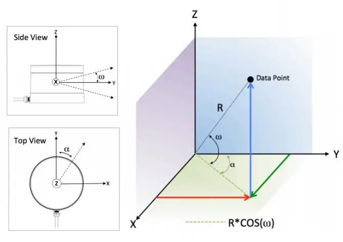
Coordinate conversion
The information in the LR-16F data package is the azimuth value and distance value established in the polar coordinate system. It’s more convenient to construct three-dimensional scene through the point cloud data by converting polar coordinate value to Cartesian coordinate system.
The above values corresponding to each channel is shown in the following table:
| Channel# | Vertical angle (ω) | Horizontal angle (α) | Horizontal offset (A) | Vertical offset (B) |
| CH0 | -15° | α | 21mm | 5.06mm |
| CH1 | 1° | α+1*0.00108*H | 21mm | -9.15mm |
| CH2 | -13 | α+2*0.00108*H | 21mm | 5.06mm |
| CH3 | 3° | α+3*0.00108*H | 21mm | -9.15mm |
| CH4 | -11 | α+4*0.00108*H | 21mm | 5.06mm |
| CH5 | 5° | α+5*0.00108*H | 21mm | -9.15mm |
| CH6 | -9 | α+6*0.00108*H | 21mm | 5.06mm |
| CH7 | 7° | α+7*0.00108*H | 21mm | -9.15mm |
| CH8 | -7 | α+8*0.00108*H | -21mm | 9.15mm |
| CH9 | 9° | α+9*0.00108*H | -21mm | -5.06mm |
| CH10 | -5 | α+10*0.00108*H | -21mm | 9.15mm |
| CH11 | 11° | α+11*0.00108*H | -21mm | -5.06mm |
| CH12 | -3 | α+12*0.00108*H | -21mm | 9.15mm |
| CH13 | 13° | α+13*0.00108*H | -21mm | -5.06mm |
| CH14 | -1 | α+14*0.00108*H | -21mm | 9.15mm |
| CH15 | 15° | α+15*0.00108*H | -21mm | -5.06mm |
Note: Under normal accuracy, the horizontal angle α only needs to increase the parameters in the table above.
The calculation formula for space coordinates is
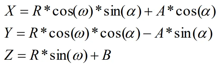
Definitions:
- The measured distance output by each channel of the LiDAR is set as R. Note that the unit of the LiDAR input is 2mm, please convert to 1mm first
- Rotating speed of LiDAR is set as H (usually 10Hz)
- The vertical angle of each channel of the LiDAR is set as ω
- The horizontal angle output by the LiDAR is set as α
- The horizontal offset of each channel of the LiDAR is set as A
- The vertical offset of each channel of the LiDAR is set as B
- The spatial coordinate system of each channel of the LiDAR is set to X, Y, Z

ABOUT COMPANY
- Morpheus Tek
- Web: www.morpheustek.com
- Email: [email protected]
- TEL: (+86) 400 102 5850


