![]()
Quick Start Use Manual 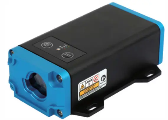
A090
Laser Distance Sensor
Sensing Reality
Electrical parameters and specifications
Table 1 Electrical characteristics
| Parameter Name | Parameter values |
| Input voltage | 7-26V |
| Average current | 100mA(Vin= 10V) |
| Peak current | <150mA(Vin= 10V) |
| Type of communication interface | RS485, CAN, 1 analog output,2 switching output, 1 switching input |
| Power consumption | <1.5W |
Table 2 Basic parameters
| Measuring principle | Phalle |
| Measuring range | 0.05-90m(90%,300Iux,single) 0.2-45m(90%,300Iux,30Hz) –I |
| Resolution | 0.1mm |
| Measurement reference | Front-end distance measuring sensor |
| Accuracy | ±1.5mm (90% diffuse reflection <20m) |
| ±3.0mm (full range) | |
| Measuring frequency | Support single measurement and continuous measurement: frequency of continuous measurement: 5Hz,10Hz,20Hz, and 30Hz are available. |
| Light source | 650-660nm |
| Laser class | Class II (laser power is between 0.75-0.95mW) |
| Typical spot size (distance) | 7mm©10m |
| Initialization lime | <1000ms |
| Holder material | Metal (aluminum) |
| Type of connection | M12,12P,Male |
| Weight(excluding accessories and packaging materials) | 350g |
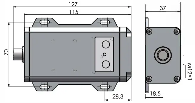
| Dimensions(width x length x height) | 79•127•31mm |
Notice: *1 The specific measurement range will change due to the measuring frequency, light intensity, and target reflectivity.
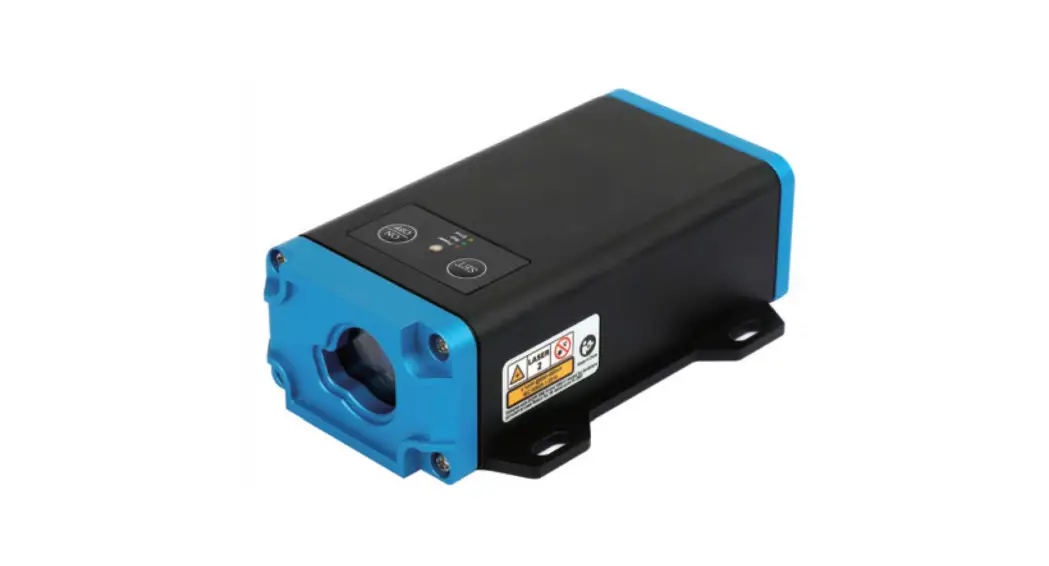
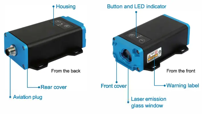
Appearance and dimension
2.1 Appearance
2.2 Installation dimension
Instruction of wiring
3.1 Description of interface terminal
The external interface adopts 12P, M12 male aviation plug, and the pin sequence is as shown in the figure below:
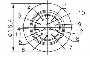
A 2m-long 12-core molding cable is included, with one end of an M 12 female aviation plug, and the other end of colored wire.
| PIN | Definition | Description |
| 2 | V+ | 7 … 26V |
| 3 | GND | av |
| 4 | 1 | Switching output channel 1, push-pull output, maximum drive current 200mA |
| 5 | 2 | Switching output channel 2, push-pull output, maximum drive current 200mA |
| 6 | VCC | 10 voltage, 12V-24V |
| 8 | 485A | 485 output A |
| 7 | 485B | 485 output B |
| 8 | Multi1 | CANH, IIC_SDA,5VIO(toggle switch to shift; program functions also need to be set to corresponding functions through parameters), default to CANH |
| 9 | Multi2 | CANL, IIC_SCL,5VIO(toggle switch to shift; program functions also need to be set to corresponding functions through parameters), default to CANL |
| 10 | INDIO | 10 ground |
| 11 | 11 | INPUT1, switching input channel 1, when not connected, it is high-level, Active low |
| 12 | analogous | Analog signal output, support -5V,0-10V,4-20mA, 0-20mA,0-24mA,parameter selection is required, default to 4-20mA out ut |
Notice:
- The 485 interfaces, CAN interface, analog output, 10 output, and input all adopt a fully isolated design. Thus do not connect VCCIO and GNDIO with V+ and GND together, otherwise, the effect of power isolation will not be achieved.
- If only 485 and CAN are used, VCCIO and GNDIO may not be connected. If the switching output and input functions are used, VCCIO and GNDIO must be connected.
- If the analog output is used, GNDIO should be taken as the reference ground.
- Communication interface description
4.1 RS485 Modbus RTU communication protocol
Please refer to “Industrial Ranging Sensor Modbus RTU Communication Protocol” for detailed information.
4.2 CAN communication protocol
The CAN communication protocol supports standard frames and extended frames; the communication parameters could be set via the RS485 bus. Please refer to “Industrial Ranging Sensor Modbus RTU Communication Protocol” for a detailed CAN communication setting method. For CAN communication protocol, please refer to “Industrial Ranging Sensor
CAN Communication Protocol”.
4.3 Analog output
There are 6 options for analog output function, namely:
=0 off
=1 0-5V
=2 0-10V
=3 4-20mA
=4 0-20mA
=5 0-24mA
The configuration parameters should be set via the RS485 bus. Please refer to “Industrial Ranging Sensor Modbus RTU Communication Protocol” for details.
4.4 Switching outputs
The switching output is in push-pull mode and supports two modes of output setting, namely (1: ON> OFF, 2: ON <OFF). The device automatically judges the mode according to the set hysteresis parameters.
1) Hysteresis parameter: ON level>OFF level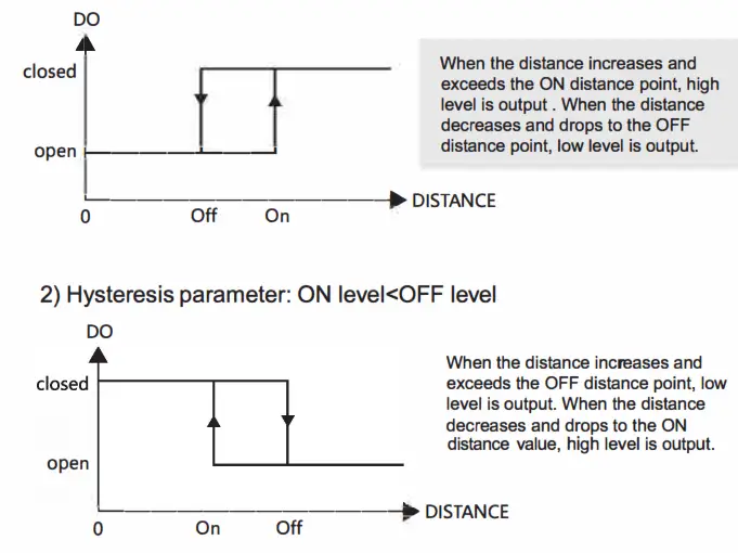 The 10 output configuration parameters should be set via the RS485 bus.
Please refer to “Industrial Ranging Sensor Modbus RTU Communication Protocol” for details.
4.5 Switching input
The functional parameters of the switching input have three modes, as shown below:
=0 off
=1 not connected or high level to start the measurement, low level to stop measurement
=2 not connected or high level to stop measurement, low level to start measurement
10 input configuration parameters should be set via the RS485 bus.
Please refer to “Industrial Ranging Sensor Modbus RTU Communication Protocol” for details.
5. Service and maintenance
Please visit the OLEI official website for inquiry of service and maintenance information;
Website: www.ole-systems.com
Path: Service and Support>>Service and maintenance
 http://weixin.qq.com/r/SCrB2WrE2zekrS66939a
MorpheusTEK Inc
Exclusive OLEI Distributor Partner
[email protected]
+1-610 883 6026


