Daviteq WSLRW-LPC-01 LoRaWAN Lidar People Counter
Thank you very much for choosing Daviteq Wireless Sensors. We are the leading wireless sensor manufacturer in the World. We have a wide range of wireless sensors which support different connectivity like LoRaWAN, Sigfox, Sub-GHz, NB-IoT…Please find out more information at this link.
This manual is applied to the following products
| Item code | HW Version | Firmware Version | Remarks |
| WSLRW-LPC-01 | 1.0 | 1.0 |
Information Changes in this version v.s previous version
| Item | Changes | Changed by | Changed Date | Approved by | Approved Date |
| 1 | Initial version | P.N.Diep | 09-05-2022 | N.V.Loc | 28-05-2022 |
To use this product, please refer step by step to the below instructions.
Operating Principle
Uplink Payload
Battery
Connect to Gateway
Installation
Troubleshooting
Configuration
Calibration
Specification
Warranty and Support
Quick Guide
Reading time: 10 minutes![]() Finish this part so you can understand and put the sensor in operation with the default configuration from the factory.
Finish this part so you can understand and put the sensor in operation with the default configuration from the factory.
What is the LoRaWAN Lidar People Counter sensor and its principle of operation?
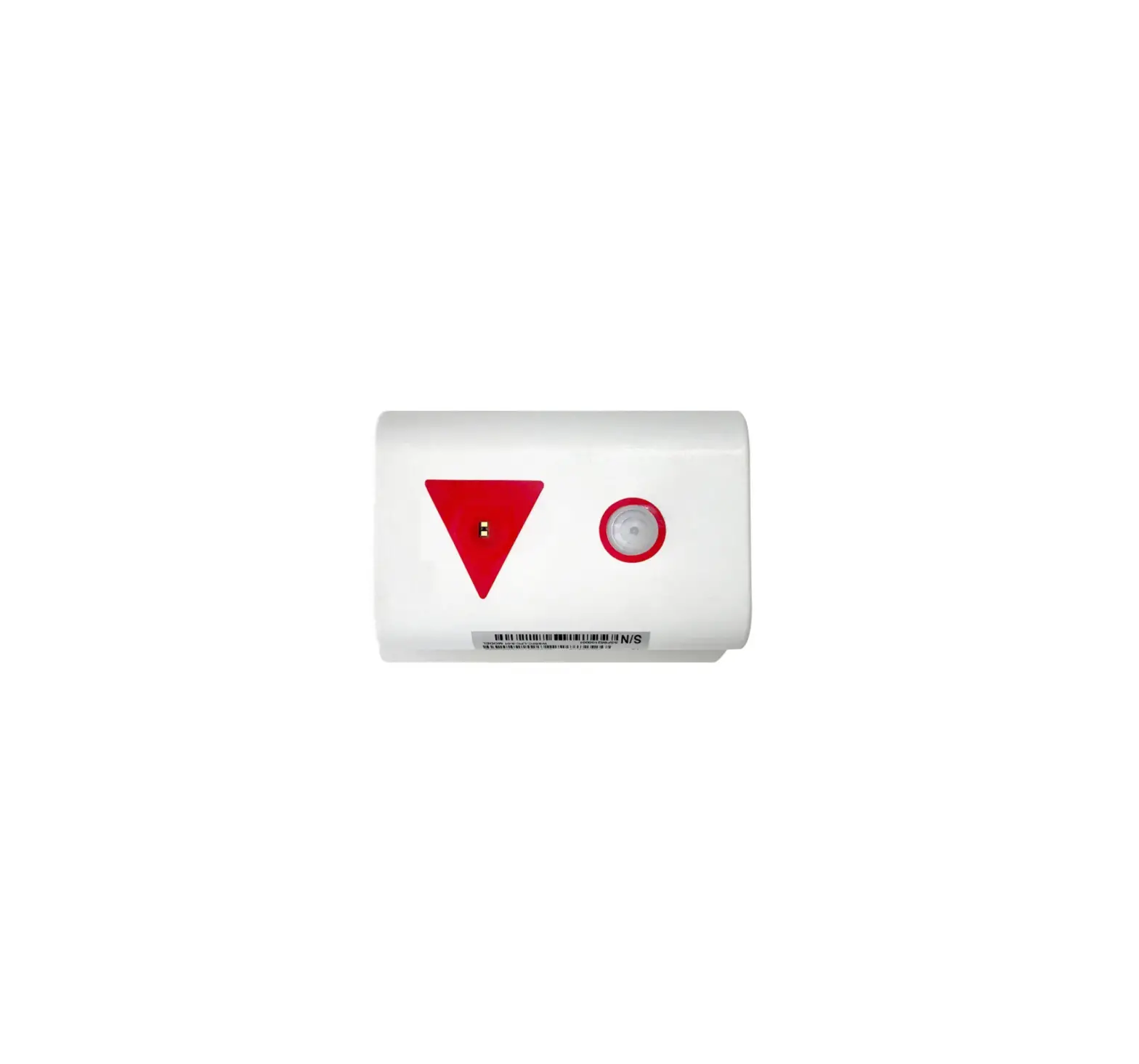
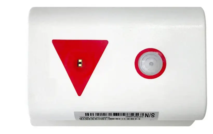
WSLRW-LPC is a LoRaWAN sensor with a built-in advanced Lidar sensor to detect and count people. It can count the people walking thru a gate in 2-way with an accuracy higher than 95%. This sensor utilizes lidar technology, which is not affected by temperature, humidity, and RF noise and is less affected by ambient light…
It is battery-operated and able to connect to any LoRaWAN gateways. It supports all frequency zones.
For the principle operation of the Lidar people counter, please refer to this link.
What are the typical applications of this sensor?
Please refer to this link for typical applications.
When does the device send uplink messages?
In most cases, the device will not send the uplink message immediately when there is a person or object passing thru the gate, as this operation will cause the battery to drain off quickly.
Instead, it will send uplink messages in the following cases:
![]() Case 1: Send an uplink message in the pre-defined cycle
Case 1: Send an uplink message in the pre-defined cycle
For example, every 10 or 30 minutes. In this case, it will send the updated counting values. There are 02 counting values in the payload:
- Resettable counter.
- Non-resettable counter.
![]() Note: we do recommend using a non-resettable counter.
Note: we do recommend using a non-resettable counter.
To change the cycle of data sending, you can change the value of the parameter: Cycle send data (default is 900 seconds)
![]() Case 2: Send an uplink message upon a certain number of people passing thru!
Case 2: Send an uplink message upon a certain number of people passing thru!
In case, if you want the device to send an uplink message upon a certain number of people passing thru the gate then you can configure the following parameter: count_threshold. The default value is 20.
What does it mean? It means when the resettable_ counter reaches the number 20 (20 people pass thru in one direction, for any direction), the device will send the uplink message. After sending, it will reset the resettable_ counter to zero for counting again in the next cycle. The count_ threshold can be configured to any value from 1.
![]() Case 3: Send uplink on demand!
Case 3: Send uplink on demand!
During commissioning the sensor, you can manually trigger the data sending by applying the Magnet key so that the device will send data immediately.
![]() Note: the time interval between the 02 triggers must be larger than 15 seconds.
Note: the time interval between the 02 triggers must be larger than 15 seconds.
In summary, the device will send the uplink messages in 03 cases:
- Case 1: when the time of the Data sending cycle is reached.
- Case 2: when the value of the resettable counter is larger than the pre-defined count threshold.
- Case 3: when the device is forced to send data by a Magnet key.
Send uplink as quickly as possible!
![]() In some special use cases, if you need the device to send an uplink message upon there is a person or object passing thru the gate, then you need to configure the following parameters:
In some special use cases, if you need the device to send an uplink message upon there is a person or object passing thru the gate, then you need to configure the following parameters:
* Count_ threshold = 1
* Sensor_ sampling_ rate = 10 (10 seconds is smallest value for battery saving)
The important configuration parameters
The sensor was pre-configured at the factory with default values for configuration parameters that meet the most use cases. However, depending on the specific use case, the customer can adjust those parameters. Please refer to section 3.2 for more details.
What kind of battery is used for this sensor?
The sensor is smart, thanks to the integrated PIR sensor. If there were no people around it will fall to the sleep stage to save battery. If there were people nearby, it will wake up in a very short time and then be ready to count people passing thru.
The sensor is powered by 6 x AA 1.5V batteries for many years of operation. We do recommend using Energizer L91 battery which is very popular and high performance. This battery has a capacity of up to 3500mAh with a working temperature range from -40 to +60 oC. The instruction for installing the batteries is in this link.
For Battery life estimation, please refer to this link.
What’s in the package?
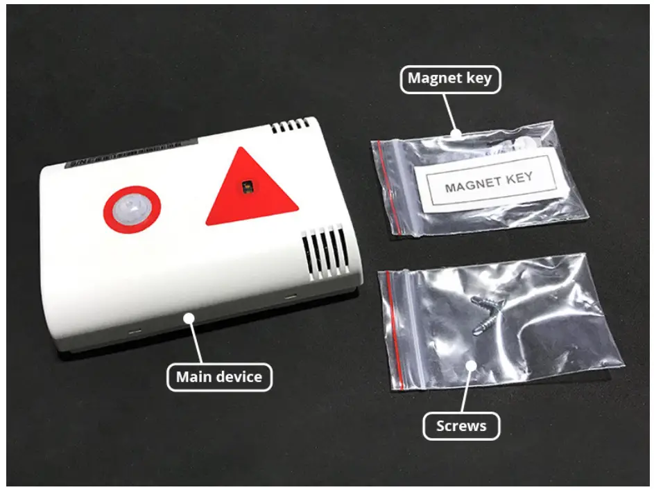
![]() The package includes:
The package includes:
01 x Lidar sensor
01 x Magnet key
02 x Self-tapping screw M4
With the default configuration, the device can be connected quickly to the Network Server by the following steps.
Step 1: Prepare the values of communication settings:
| Frequency zone | Most of the sensor was configured the frequency-zone to suit customer application before delivery |
| DevEUI | Get the DevEUI on the product nameplate |
| AppEUI | Default value: 010203040506070809 |
| AppKey | Default value: 0102030405060708090A0B0C0D0E0F10 |
| Activation Mode | OTAA with local join server |
| Network Mode | Public |
| LoraWAN Protocol version | 1.0.3 |
| Class | A |
![]() Note: If the above settings do not match your network server/application, please refer to section 3.2 Sensor configuration to change the settings
Note: If the above settings do not match your network server/application, please refer to section 3.2 Sensor configuration to change the settings
Step 2: Register the device on the LoRaWAN network server.
Input the above settings on your device registration page of the network server.
![]() Note: Different network server software will have different processes for registering the device. Please refer to the manual of the network server software being used for more details.
Note: Different network server software will have different processes for registering the device. Please refer to the manual of the network server software being used for more details.
Please visit this link to get the instructions for adding the LoRaWAN sensors to some common network servers such as Actility, TTN…
Step 3: Install the batteries to the device
Refer to this link for details.
![]() After installing the battery in 60 seconds, the first data packet will be sent to the LoRaWAN gateway. After receiving the first data packet, the time of another packet depends on the value of the parameter: cycle_send_data. Additionally, you can use a Magnet Key to force the device to send data instantly
After installing the battery in 60 seconds, the first data packet will be sent to the LoRaWAN gateway. After receiving the first data packet, the time of another packet depends on the value of the parameter: cycle_send_data. Additionally, you can use a Magnet Key to force the device to send data instantly
Step 4: Decode the payload of receiving package
Please refer to section1.4 Uplink Payload and Data Decoding for details of decoding the receiving packet.
Uplink Payload and Data Decoding
For the Uplink Payload structure, please refer to this link.
![]() Note: Please select the right Payload document to suit the FW version of the sensor
Note: Please select the right Payload document to suit the FW version of the sensor
Sensor Installation
![]() ATTENTION:
ATTENTION:
- DO NOT INSTALL THE SENSOR OUTDOOR OR INDOORS WITH HIGH INTENSITY OF SUNLIGHT;
- DO NOT INSTALL THE SENSOR AT A PLACE WHERE HIGH DUST PARTICLES OR STEAM AFFECT THE OPTICAL SENSOR;
- DO NOT INSTALL THE SENSOR AT A PLACE WHERE THE PEOPLE MOVING IN PARALLEL AND NEARBY THE SENSOR, THAT WILL CAUSE THE SENSOR TO WAKE UP ALL THE TIME, BUT NOT FOR COUNTING PEOPLE. THIS PROBLEM WILL MAKE THE BATTERIES DRAIN OFF QUICKLY IN A FEW DAYS.
WARNING:
- Avoid placing hands or heavy objects on the laser sensor surface or the PIR sensor surface, as this may cause damage to the device;
- Periodically use a clean cloth moistened with 70 degrees of alcohol to wipe the surface of the 2 sensors to keep the sensor clean and accurate.
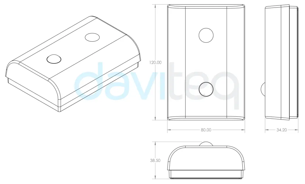
DEVICE DIMENSIONS
Mounting sensor on the ceiling
![]() Please take note of the direction of people entering the room of the sensor
Please take note of the direction of people entering the room of the sensor
Then follow this link for instructions on mounting the sensor on the ceiling.
Battery Installation
Please follow the instructions in this link.
Sensor calibration
Depending on the height of installation, the distThreshold parameter may need to change to an appropriate value so that the sensor can count accurately.
Please follow the steps in this link.
Maintenance
Troubleshooting
Problems with LoRaWAN communication like not receiving the packets…please refer to this link to troubleshoot the device.
Problems with the sensor functions like not measuring, or inaccurate measuring….please refer to this link to troubleshoot the sensor part.
Sensor maintenance
| Maintenance works | Yes/No | Descriptions |
| Consumable parts replacement | No | The lidar sensor is not a consumable part, there is no need to replace the sensor module |
| Cleaning sensor or device | Yes | Check and clean the surface of the lidar sensor and PIR sensor. Please refer to this link; |
| Re-calibration / Re-validation | No |
Advanced Guide
Operating principle of LoRaWAN Lidar People Counter
Operating principle of the complete device
The Daviteq LoRaWAN Lidar People Counter comprises 02 parts linked internally as shown below picture.
- The Daviteq LoRaWAN module;
- The Daviteq Lidar People Counter:
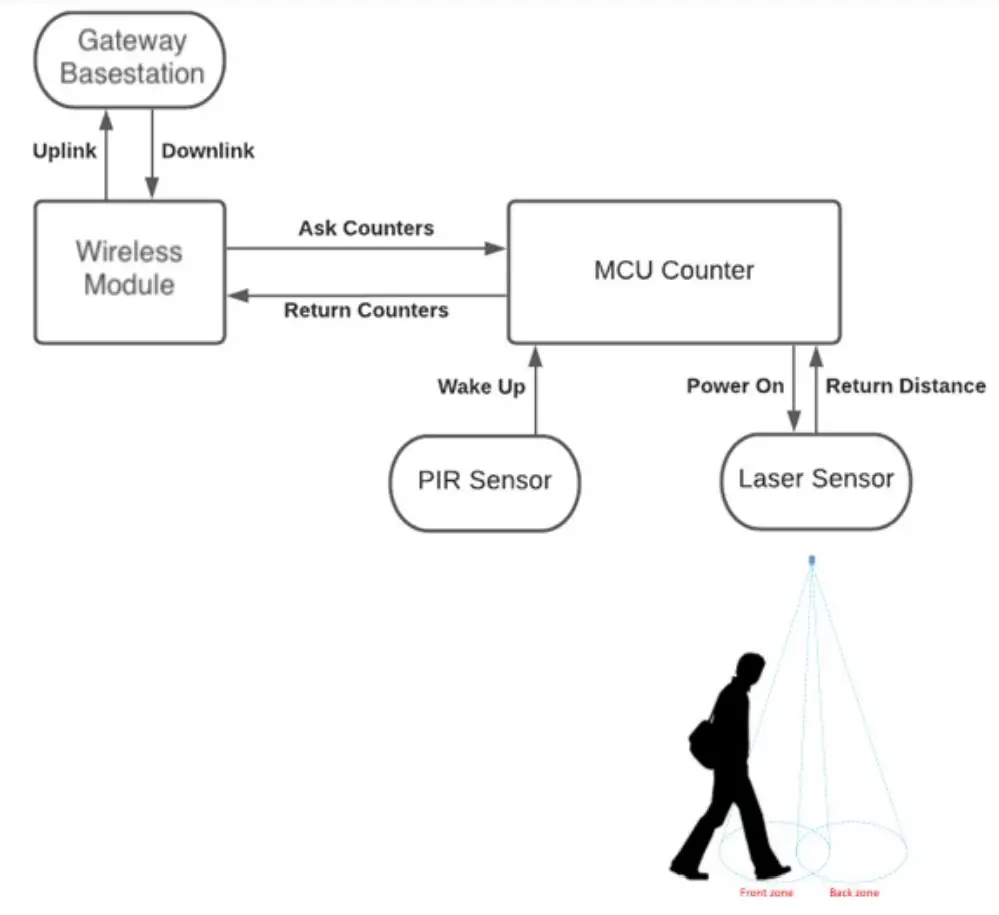
The people counting module is working independently from the wireless module. That means while the counting module is counting people, the wireless module may be in sleep mode to save battery. The wireless module will wake up and read data from the counting module to check the counting value periodically (120 seconds as default, configurable) to see whether the counter increase so that it will decide to send a message or not. The 120 s is the default value of parameter sensor_sampling_rate. You can reduce this value, but smaller value, shorter battery life!
The device will send the uplink messages in 03 cases:
- Case 1: when the time of the Data sending cycle is reached.
- Case 2: when the value of the resettable counter is larger than the pre-defined count threshold.
- Case 3: when the device is forced to send data by a Magnet key.
Operating principle of Lidar People Counting Module
To understand how Lidar technology can count people, please refer tothis link for a complete understanding of this measuring technique.
Some important configuration parameters
Below are some important configuration parameters which affect the operation of the device.
- sampling_rate | Default = 120s
The counting module is working independently from the wireless module. That means while the counting module is counting people, the wireless module may be in sleep mode to save battery. The wireless module will wake up and read data from the counting module to check the counting value periodically (120 seconds as default, configurable) to see whether the counter increase so that it will decide to send a message or not. The 120 s is the default value of parameter sensor_sampling_rate. You can reduce this value, but smaller value, shorter battery life! - count_threshold | Default = 20
With this threshold, the device will send an uplink message when the resettable_counter reaches this threshold. After sending, the resettable _counter will be reset to zero again. - distThreshold | Default = 1600mm
Change this parameter to suit the height of the sensor - cycle_send_data | Default = 3600s
Interval time to send an uplink message regardless of any conditions
Those configuration parameters can be changed by downlink or offline tools. For more other configuration parameters, please refer to the next section.
Sensor Configuration
How to configure the LoRaWAN Lidar People Counter?
Method 1: Configuring via Downlink message. Please find the instructions inthis link, but please take note of the FW version of the Document.
Method 2: Configuring via offline cable.
![]() Note: THE SENSOR IS ONLY ACTIVE FOR OFFLINE CONFIGURATION IN THE FIRST 60 SINCE POWER UP BY BATTERY OR PLUGGING THE CONFIGURATION CABLE.
Note: THE SENSOR IS ONLY ACTIVE FOR OFFLINE CONFIGURATION IN THE FIRST 60 SINCE POWER UP BY BATTERY OR PLUGGING THE CONFIGURATION CABLE.
What parameters of the device are configured?
- Some parameters are read-only, and some are read and writeable.
- To read the parameters, use the off-line cable as above instruction.
- To write the parameters, use the off-line cable or downlink as above instructions.
Below tables are the lists of the parameters of the device.
Read-only Parameter Table
| Modbus Register (Decima
| Modbus Register (Hex)
| Function Code
| # of Register | Description | Range | Default | Format | Property | Comment |
| 0 | 0 | 3 | 5 | device info | WSLRW- I2C | string | Read | Wireless Sensor LoRaWAN – I2C | |
| 5 | 5 | 3 | 4 | firmware version | 1.00ddmm
| string | Read | ddmm = day / month | |
| 9 | 9 | 3 | 2 | hardware version | 1.10 | string | Read | ||
| 11 | B | 3 | 4 | lorawan protocol version | 01.01.00 | string | Read | LoRaWAN v1.1.0 | |
| 15 | F | 3 | 6 | application version | 01.03.00.0
| string | Read | application server v1.3.0.0 | |
| 21 | 15 | 3 | 6 | mac layer version | 04.04.02.0
| string | Read | mac layer v4.4.2.0 | |
| 27 | 1B | 3 | 4 | deviceEUI | hex | Read | End Device’s EUI number, used to register the product on the Network Server by OTAA | ||
| 31 | 1F | 3 | 4 | Lora appEUI | hex | Read | Application server’s EUI number is used to register the product on the Network Server by OTAA | ||
| 35 | 23 | 3 | 8 | Lora appKey | hex | Read | The number of keys used to create two security keys of the End Device, used to register the product on the Network Server by OTAA | ||
| 43 | 2B | 3 | 8 | Lora nwkSkey | hex | Read | key number encrypts the communicatee command of the MAC layer of the End Device, which is used to register the product on the Network Server by ABP
| ||
| 51 | 33 | 3 | 8 | Lora appSkey | hex | Read | End Device data encryption key number, used to register the product on the Network Server by ABP | ||
| 59 | 3B | 3 | 2 | device address | 0 | uint32 | Read | End Device address created by the Application server, used to register the product on the Network server by ABP | |
| 61 | 3D | 3 | 2 | network ID | 0 | uint32 | Read | Network server ID number, used to register the product on the Network server by ABP | |
| 63 | 3F | 3 | 2 | join mode | OTAA | string | Read | OTAA: Over- the-Air activation, ABP: Activation by Personalistic  | |
| 65 | 41 | 3 | 4 | network mode | PUBLIC | string | Read | PUBLIC, PRIVATE | |
| 69 | 45 | 3 | 3 | region code | AS923 | string | Read | 1: AS923, 2: KR920, 3: AU915, 4: US915, 5: EU868, 6: IN865, 7: RU864, 8: CN779, 9: CN470, 10: EU433 | |
| 72 | 48 | 3 | 4 | data rate | DR2:980 | string | Read | DR0:250, DR1:440, DR2:980, DR3:1760, DR4:3125, DR5:5470 | |
| 76 | 4C | 3 | 3 | bandwidth | BW125 | string | Read | BW125, BW250, BW500 | |
| 79 | 4F | 3 | 2 | spread factor | SF10 | string | Read | SF12, SF11, SF10, SF9, SF8, SF7 | |
| 81 | 51 | 3 | 4 | activation of ADR | ADR OFF | string | Read | ADR ON, ADR OFF | |
| 85 | 55 | 3 | 1 | class | A | string | Read | ||
| 103 | 67 | 3 | 1 | sensor type | 1-255 | uint16 | Read | 1-254: sensor type, 255: no sensor | |
| 104 | 68 | 3 | 1 | battery level | 0-3 | uint16 | Read | 4 levels of battery capacity status |


Read/Write Parameter Table
![]() Note: Please check the column Property for identifying which parameter request a password for writing a new value. In this case, the user needs to input the password (190577) into the parameter name “password for setting” at address 268.
Note: Please check the column Property for identifying which parameter request a password for writing a new value. In this case, the user needs to input the password (190577) into the parameter name “password for setting” at address 268.
| Modbus Register (Decim
| Modbus Register (Hex) | Function Code | # of Register | Description | Range | Default | Format | Property | Comment |
| 256 | 100 | 3 / 16 | 1 | Modbus address | 1-247 | 1 | uint16 | R/W | Modbus address of the device |
| 257 | 101 | 3 / 16 | 1 | Modbus baudrate | 0-1 | 0 | uint16 | R/W | 0: 9600, 1: 19200 |
| 258 | 102 | 3 / 16 | 1 | Modbus parity | 0-2 | 0 | uint16 | R/W | 0: none, 1: odd, 2: even |
| 259 | 103 | 3 / 16 | 9 | serial number | string | R/W (Password) | |||
| 268 | 10C | 3 / 16 | 2 | password for setting | uint32 | R/W (Password) | password 190577 | ||
| 270 | 10E | 3 / 16 | 4 | Lora appEUI | hex | R/W (Password) | Application server’s EUI number, used to register the product on the Network Server by OTAA | ||
| 274 | 112 | 3 / 16 | 8 | Lora appKey | hex | R/W (Password) | The number of keys used to create two security keys of the End Device, used to register the product on the Network server by OTAA |
| 282 | 11A | 3 / 16 | 8 | Lora nwkSkey | hex | R/W (Password) | key number encrypts the communication command of the MAC layer of the End Device, which is used to register the product on the Network Server by ABP | ||
| 290 | 122 | 3 / 16 | 8 | Lora appSkey | hex | R/W (Password) | End Device data encryption key number, used to register the product on the Network Server by ABP | ||
| 298 | 12A | 3 / 16 | 2 | device address | uint32 | R/W (Password) | End Device address created by the Application server, used to register the product on the Network server by ABP | ||
| 300 | 12C | 3 / 16 | 2 | network ID | uint32 | R/W (Password) | Network server ID number, used to register the product on the Network server by ABP | ||
| 302 | 12E | 3 / 16 | 1 | activation mode | 0-1 | 1 | uint16 | R/W (Password) | 1: OTAA (Over-the-Air Activation), 0: ABP (Activation by Personalization) |
| 304 | 130 | 3 / 16 | 1 | application port | 1-255 | 1 | uint16 | R/W (Password) | Port 224 is reserved for certification |
| 305 | 131 | 3 | 16 | 1 | network mode | 0-1 | 1 | uint16 | 1: Public, 0: Private |
| 317 | 13D | 3 / 16 | 1 | region | 1-7 | 1 | uint16 | Read/Write(P | 1: AS923, 2: KR920, 3: AU915, 4: US915, 5: EU868, 6: IN865, 7: RU864, 8: CN779, 9: CN470, 10: EU433 |
| 318 | 13E | 3 / 16 | 1 | data rate | 7 | uint16 | R/W (Password) | 0: 250 bps, 1: 440 bps, 2: 980 bps, 3: 1760 bps, 4: 3125 bps, 5: 5470 bps | |
| 319 | 13F | 3 / 16 | 1 | tx power | 2-20 | 16 | uint16 | R/W (Password) | tx power: 2,4,6,8,10,12,14,16,18, |
| 320 | 140 | 3 / 16 | 1 | adaptative data rate | 0-1 | 0 | uint16 | R/W (Password) | Automatically adjust data rate, 0: disable, 1: enable |
| 334 | 14E | 3 / 16 | 2 | cycle send data | 900 | uint32 | R/W | sec (data sending cycle) | |
| 340 | 154 | 3 / 16 | 2 | sensor1: sampling_r | a | 120 | uint32 | R/W | sec (frequency of data taken from sensor 1) |
| 384 | 180 | 3 | 16 | count_thres | 20 | uint16 | Threshold count on how many people send Gateway |
| 385 | 181 | 3 | 16 | dist_thresh
| o | 1600 | uint16 | Threshold setting for laser sensor to distinguish between when people are present and when no one is standing under the sensor. The laser sensor will measure the distance value from the sensor (ceiling) to the floor. + When there are people, the measured laser sensor value < Dist_ threshold + When there is no person, the measured laser sensor value > Dist _threshold | |
| 386 | 182 | 3 | 16 | dist_hys | 100 | uint16 | Hysteresis of Dist_ threshold | ||
| 387 | 183 | 3 | 16 | inter_meas_
| 48 | uint16 | The sampling time of the sensor laser |
Calibration or commissioning for Lidar people counting sensor
Please refer to this link.
Product specification
Please refer to the detailed specifications in this link.
Warranty and Support
For warranty terms and support procedures, please refer to this link.
References
Use-cases:
Case studies:
White-papers:
END.
References
 Common notes in instal... | Online Product Manuals & Datasheets
-
Common notes in instal... | Online Product Manuals & Datasheets
-
Common notes in instal... | Online Product Manuals & Datasheets
-
Manual for LoRaWAN Lid... | Online Product Manuals & Datasheets
-
Manual for LoRaWAN Lid... | Online Product Manuals & Datasheets
-
Manual for LoRaWAN Lid... | Online Product Manuals & Datasheets
-
Manual for LoRaWAN Lid... | Online Product Manuals & Datasheets
-
Manual for LoRaWAN Lid... | Online Product Manuals & Datasheets
-
Manual for LoRaWAN Lid... | Online Product Manuals & Datasheets
-
Manual for LoRaWAN Lid... | Online Product Manuals & Datasheets
-
Manual for LoRaWAN Lid... | Online Product Manuals & Datasheets
-
Manual for LoRaWAN Lid... | Online Product Manuals & Datasheets
-
Manual for LoRaWAN Lid... | Online Product Manuals & Datasheets
-
Offline configuration ... | Online Product Manuals & Datasheets
-
Troubleshooting for Lo... | Online Product Manuals & Datasheets
-
Warranty term and Supp... | Online Product Manuals & Datasheets
-
daviteq.com/en/manuals/uploads/images/gallery/2022-06/AP8EMM2hQc2mpK26-VNvo1EokJP0eP053-WSSFC-LPC-H12.png
-
daviteq.com/en/manuals/uploads/images/gallery/2022-06/AWyqqtFZZHUB20At-UkUuDHEep3q1T9eq-WSSFC-LPC-DMS.png
-
daviteq.com/en/manuals/uploads/images/gallery/2022-06/M99VnaEPODDADq4K-block-diagram-of-wireless-people-counter.png
-
daviteq.com/en/manuals/uploads/images/gallery/2022-06/qxONRWvzZnPPTPRD-269032-aabatteries-energizer-ultimatelithiumaa.webp
-
daviteq.com/en/manuals/uploads/images/gallery/2022-07/1d02HiPYGAmb6weQ-Untitled-1.jpg
-
daviteq.com/en/manuals/uploads/images/gallery/2022-07/KJKvTbFf11wdtSY1-MicrosoftTeams-image-(124).png
-
Online Product Manuals & Datasheets
-
Daviteq – Nhà sản xuất cảm biến đo lường và hệ thống IoT
-
LoRaWAN Lidar People Counter WSLRW-LPC | DAVITEQ


