![]()
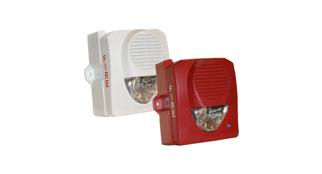
SH-24H-WP SERIES High Intensity Weatherproof Select-A-Strobe-Horn
Owner’s Manual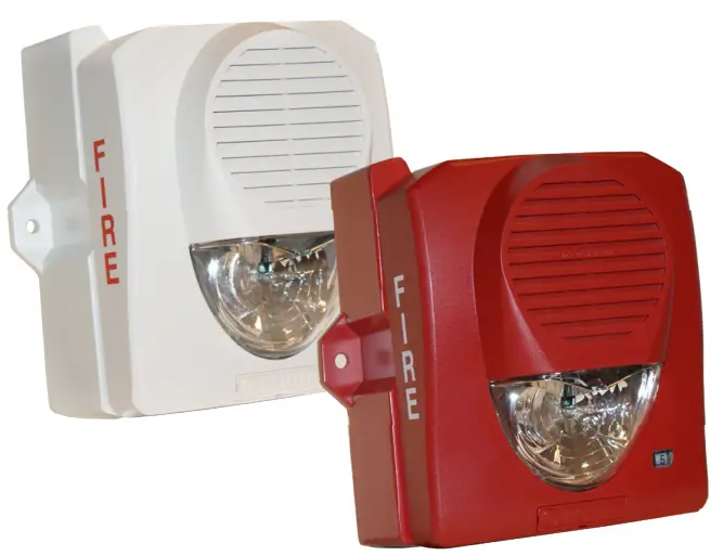
![]()
SH-24H-WP SERIES
HIGH INTENSITY WEATHERPROOF
SELECT-A-STROBE/HORN®
SH-24H-WP SERIES High Intensity Weatherproof Select-A-Strobe-Horn
- UL and cUL listed
- 24 VDC with 95, 110, 135, 150, 177 or 185 cd settings
- 6 distinct candela settings
- Candela selection view window
- 33 sound output settings
- Horn or chime sound output
- Pre-wire back plate
- Universal back plate mounting (single gang, double gang, octagon, or 4” square)
- Outdoor installations require a weatherproof backbox
- Single screw mounting
- Wall mount
- Indoor or outdoor (requires weatherproof back box)
- Low current draw
The SH-24H-WP Select-A-Strobe/Horn™ Series provides a wide range of candela light output options in a single device. The candela settings include a 24 volt DC operation for the 95, 110, 135, 150,
177 or 185 setting. The candela setting is displayed through the front window and is selectable using a drum wheel.
The horn settings include Temporal, Non-Temporal, March Time and a Chime sound. The horn also has Low, Mid and High volume settings for each pattern and tone. The tones include 2400 Hz, Electro Mechanical, Broadband and Chime.
The voltage input can be either regulated DC or full wave rectified (FWR) 24 volt operation with an operating range from 16 to 33 VDC.
The strobes can be synchronized using a control panel with the Potter (Maseko) sync protocol or a SMD10-3A sync module.
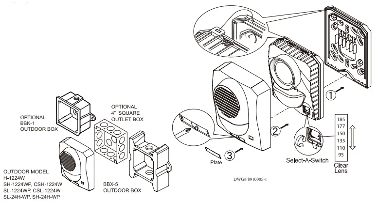
The SH-24H-WP utilizes a universal mounting plate that will mount on a single gang, double gang, octagon and 4” square electrical boxes. The back plate allows the installer to mount the plate and connect the wire connections. The strobe attaches in a hinge fashion from the top and is secured by a single mounting screw. The strobe completely
covers the mounting back plate, therefore it can be mounted before other trades work is completed and not affect the final look.
The Potter SH-24H-WP is listed for both outdoor and indoor installations. For outdoor installations the device must be mounted on a matching BBX-5 back box or a BBK-1 bell back box.
Installation
![]()
A jumper plug is provided to test for correct wiring in the supervisory mode only. Do not pass alarm current through the jumper.
Note: Installation must comply in accordance with applicable standards.
| Stock Number | Model Number | Description | Color |
| 4710012 | SH-24H-WP-R | Selectable strobe/horn/chime | Red |
| 4710013 | SH-24H-WP-W | Selectable strobe/horn/chime | White |
| 4270048 | BBX-5R | Weatherproof backbox | Red |
| 4270049 | BBX-5W | Weatherproof backbox | White |
| 1500001 | BBK-1 | Bell backbox | Red |
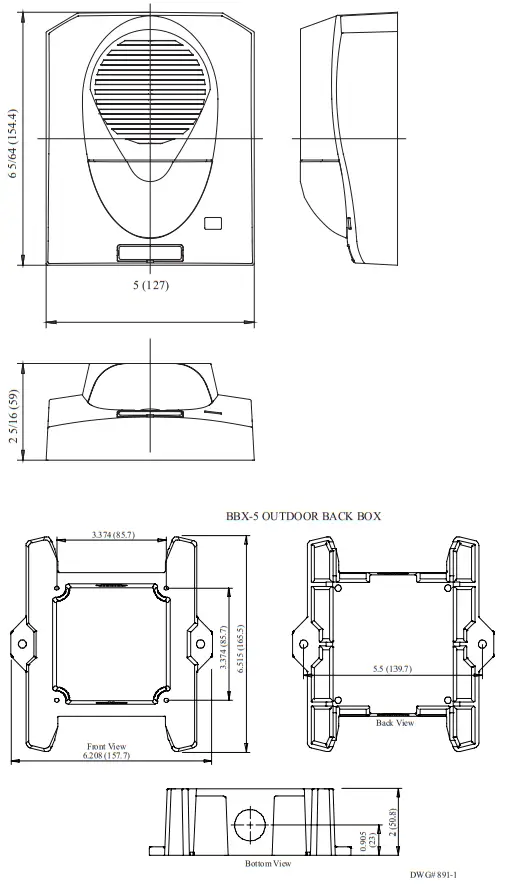
Dimensions: inches (mm)
 Light output in percentage when measured from the following directions per UL 1971.
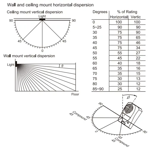
![]()
High voltage may be present inside the light assembly even though power is not connected. If access to the component board is required (removal or replacement), the capacitor must be discharged by touching a wire to both ends of the flashtube. DO NOT attempt to touch or move the assembly until the capacitor has been discharged.
Specifications
Strobe Current
| Light Output | Max. RMS Operating Current (mA RMS) | |
| Reg. 24 VDC | Reg. 24 FWR | |
| 95cd | 151 | 201 |
| !Wed | 161 | 215 |
| I 35cd | 178 | 235 |
| 150cd | 190 | 248 |
| 177cd | 218 | 283 |
| 185cd | 226 | 291 |
Note: To determine total current draw, add desired strobe setting and horn selection. Refer to the installation instructions for further information.
Horn Dipswitch
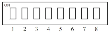 Pattern
1 ON – Non-temporal
1 OFF – Temporal
Both 2 = OFF
1 and 2 ON = March Time
Tone
3 and 4 ON = 2400Hz
3 ON and 4 OFF = Electromechanical
3 and 4 OFF = Chime
3 OFF and 4 ON = Broadband
Volume
5 and 6 ON = High
5 ON and 6 OFF = Mid
5 and 6 OFF = Low
7 and 8 ON = Horn/strobe on 2 wires
7 and 8 OFF = Horn and strobe on 4 wires
Non-Temporal Horn Current
| Pattern | Volume | Max. RMS Current (mA RMS Current) | dB Reverberant Ratings per UL464 (dB @ 10 ft.) | dB Anechoic Ratings per CAN/ULC S525 (dB @ 10 ft.) | |
| Reg 24 VDC | Reg 24 FWR | Reg 24 VDC | Reg 24 VDC | ||
| 2400 Hz | High | 87 | 236 | 87 | 100 |
| Mid | 28 | 140 | 82 | 96 | |
| Low | 18 | 77 | 80 | 92 | |
| Electro-Mechanical | High | 81 | 231 | 87 | 100 |
| Mid | 26 | 127 | 84 | 97 | |
| Low | 16 | 68 | 80 | 93 | |
| Broadband | High | 78 | 261 | 86 | 102 |
| Mid | 26 | 112 | 82 | 98 | |
| Low | 16 | 69 | 79 | 95 | |
| Chime | High | 21 | 42 | 70 | 86 |
| Mid | 8 | 20 | 62 | 80 | |
| Low | 7 | 18 | 57 | 75 | |
Temporal Horn Current
| Pattern | Volume | Max. RMS Current (mA RMS Current) | dB Reverberant Ratings per UL464 (dB @ 10 ft.) | dB Anechoic Ratings per CAN/ULC S525 (dB @ 10 ft.) | |
| Reg 24 VDC | Reg 24 FWR | Reg 24 VDC | Reg 24 VDC | ||
| 2400 Hz | High | 87 | 288 | 82 | 100 |
| Mid | 30 | 181 | 79 | 96 | |
| Low | 18 | 79 | 75 | 92 | |
| Electro-Mechanical | High | 80 | 275 | 82 | 101 |
| Mid | 27 | 138 | 80 | 96 | |
| Low | 16 | 74 | 76 | 93 | |
| Broadband | High | 80 | 289 | 82 | 102 |
| Mid | 26 | 144 | 78 | 98 | |
| Low | 16 | 61 | 76 | 95 | |
| Chime | High | 21 | 49 | 70 | 86 |
| Mid | 9 | 21 | 61 | 79 | |
| Low | 8 | 15 | 55 | 76 | |
March Time Horn Current
| Pattern | Volume | Max. RMS Current (mA RMS Current) | dB Reverberant Ratings per UL464 (dB @ 10 ft.) | dB Anechoic Ratings per CAN/ULC S525 (dB @ 10 ft.) | |
| Reg 24 VDC | Reg 24 FWR | Reg 24 VDC | Reg 24 VDC | ||
| 2400 Hz | High | 92 | 274 | 84 | 100 |
| Mid | 31 | 158 | 81 | 96 | |
| Low | 19 | 72 | 77 | 92 | |
| Electro-Mechanical | High | 86 | 274 | 83 | 100 |
| Mid | 27 | 147 | 81 | 96 | |
| Low | 19 | 80 | 77 | 93 | |
| Broadband | High | 77 | 302 | 84 | 102 |
| Mid | 28 | 135 | 80 | 98 | |
| Low | 16 | 62 | 77 | 95 | |
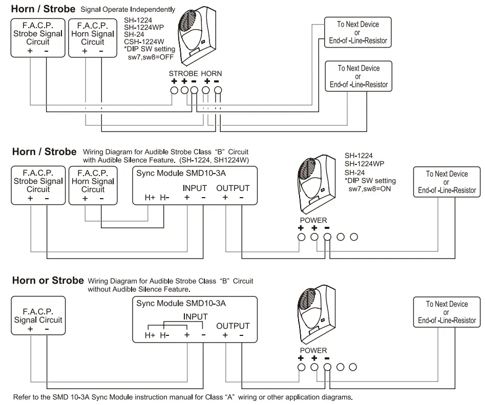
Wiring Diagram
Wiring Observe Polarity Use both terminals (or Lead) for connection. Break wire run to provide electrical supervision.
Engineering Specifications
The installer shall provide and install the Potter SH-24H-WP Selecta-Strobe/Horn™. The strobe shall have six (6) candela settings. The candela settings shall be selectable using a drum roller and shall display the candela setting on the front of the device. The horn shall have 33 selectable settings configurable by dip switches. The sounder shall be capable of ANSI Temporal Code 3, March Time and produce a chime output. The horn shall have three distinct volume levels. The strobe/horn shall operate at 24 VDC regulated or full wave rectified. The strobe/horn shall have an operating range between 16 and 33 VDC. the strobes an by synchronized using a control panel with the Potter sync protocol or the SMD10-3A sync module. The strobe shall utilize a mounting plate that allows the installer to pre-wire the mounting plate. The mounting plate shall be universal and mount on a single gang, double gang, octagon or 4 inch square box. The Potter SH24H-WP is listed for both outdoor and indoor applications. For outdoor installations, the device must be mounted on a matching BBX-5 or BBK-1 outdoor bell back box. The mounting plate shall be completely covered by the strobe and shall be secured by a single screw. The strobe shall be UL listed to standard 1638, General Signaling, and standard 1971, Signaling Devices for the Hearing Impaired. In addition, the strobes shall be cUL listed to CAN-ULC S526. The horn shall be UL listed to standard 464, Audible Signaling Devices.
![]() PRINTED IN USA
PRINTED IN USA
MKT. #8910010 – Rev C
firealarmresources.com


