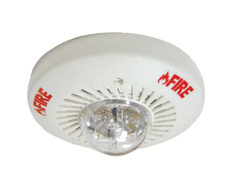
POTTER SH24C-3075110 Selectable Candela Ceiling Horn Strobe Owner’s Manual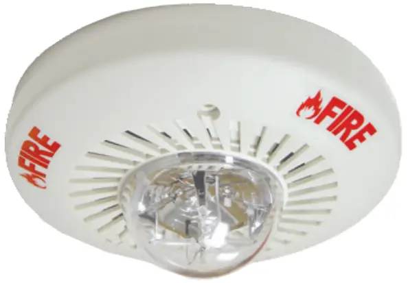
Features
- Meets or exceeds NFPA/ANSI Standards and ADA Accessibility Guidelines
- UL Listed for ceiling and wall mounting
- Screw terminal capacity up to AWG #12
- Designed for use in sleeping and non-sleeping areas
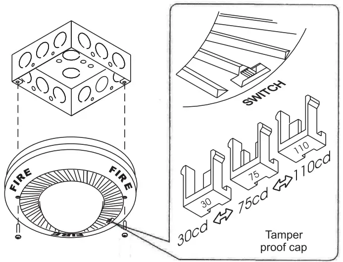
- Selectable settings: 30cd,75cd, or 110cd output
- Horn field selectable tones: 3000 Hz interrupted or electro-mechanical
Temporal or non-temporal
High or low dBA output - Mounts to 4” square, single gang, double gang, or octagonal back box; SPC-1 (retrofit plate) and RBX-1 (back box skirt) are optional
- Tamper-proof candela selector switch
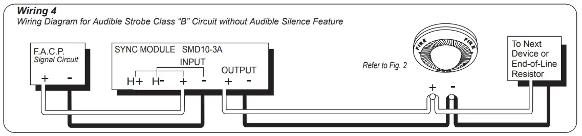
- Synchronization requires SMD10-3A Sync module
- Available in red or white housing
The SH24C series features a unique candela intensity field selector switch for alternating the candela to 30cd, 75cd, or 110cd.
The horn provides two different field selectable tones, and a high/low output setting that can be achieved with the use of mini-jumpers located on the back of the unit.
These appliances are polarized for connecting to supervised fire alarm circuits.
The strobe is designed with a xenon flash tube and provides a candela intensity field selector switch for maximum performance.
The SH24C-3075110 can be synchronized by using the SMD10-3A Sync Module to comply with NFPA recommendations concerning photosensitive epilepsy when installing more than two visual appliances within the field of view.
The strobe signals are listed for indoor use, wall mount, under UL 1971 Standard and are ADA compliant.
Engineering Specifications
The audible and visual alarm indicating appliances shall be Potter Model SH24C-3075110 or equivalent device.
The strobe shall be listed under UL 1971 Standard for signaling devices for the hearing impaired and shall be approved for fire protective service.
The candela output shall be field selectable, having three settings of 30cd, 75cd, and 110cd output.
The signaling strobe shall operate on 24V DC from a noncoded, regulated DC supply or full-wave rectified, unfiltered supply.
The horn may operate on a 24V DC coded system.
The strobe shall be designed to produce one signal flash per second with continuously applied minimum voltage.
The strobe/horn may have a SPC-1 universal back mounting plate, capable of ceiling and wall mounting to a back box.
When strobe synchronization is required, the strobe/horn shall be compatible with the Potter SMD10-3A (daisy chain) or other source of Potter sync protocol.
Audible and visual signaling devices shall be installed in accordance with current NFPA guidelines.
Ordering Information
| Model Number | Stock Number | Housing Color | Input Voltage | Operating Voltage Range | Selectable Strobe Output (cd) | Horn Sound Output | Flash Rate | Mounting Type | Operating Temperature Range |
| SH24C-3075110R | 4570003 | Red | Regulated 24V DC/ FWR | 16-33 VDC 16-33 VFWR | 30,75,110 | Selectable | 60 times/ min. | Ceiling and Wall | 32°F – 120°F (0°C – 49°C) |
| SH24C-3075110W | 4570004 | White |
Dimensions: inches (mm)
Front View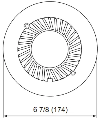
Side View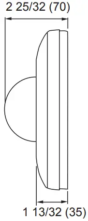
Back View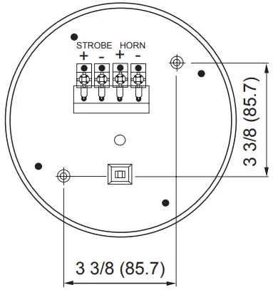
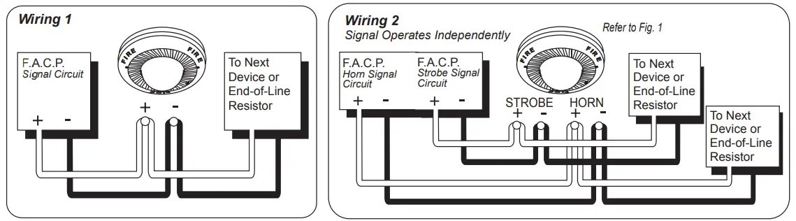
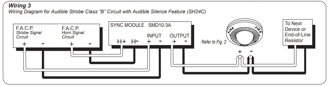
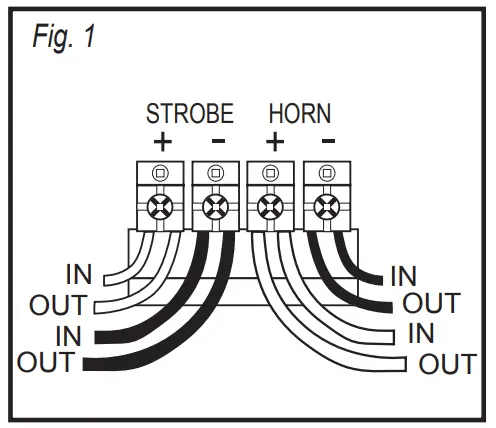
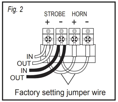
Wiring Diagram
| UL Required Minimum Light Output | Ceiling Mount | |||
| 30cd | 75cd | 110cd | ||
| DEGREES | 0 | 30.00 | 75.00 | 110.00 |
| 5-25 | 27.00 | 67.50 | 99.00 | |
| 30-45 | 22.50 | 56.25 | 82.50 | |
| 50 | 16.50 | 41.25 | 60.50 | |
| 55 | 13.50 | 33.75 | 49.50 | |
| 60 | 12.00 | 30.00 | 44.00 | |
| 65-70 | 10.50 | 26.25 | 38.50 | |
| 75-80 | 9.00 | 22.50 | 33.00 | |
| 85-90 | 7.50 | 18.75 | 27.50 | |
| Compound 45 | 7.20 | 18.00 | 26.40 | |
| Sound Output Dispersion (dB) | Horizontal | Vertical | |
| DEGREES | +90 | -2 | -5 |
| +60 | 0 | -2 | |
| +30 | 1 | -1 | |
| 0 | 0 | 0 | |
| -30 | -2 | -1 | |
| -60 | -3 | -2 | |
| -90 | -6 | -5 | |
Specifications
| Strobe/Horn Current Draw Table | PC3: Pattern PC2: Tone PC1: Volume | Maximum RMS Operating Current (mA) | Minimum Sound Output (dBA at 10ft per UL464) | ||||||
| PC3 | PC2 | PC1 | Regulated 24V DC (Typical) | Regulated 24V FWR (Typical) | Regulated 24V DC | ||||
| Horn & Strobe 30cd | Non-Temporal | Electro Mechanical | HIGH | 1 | 1 | 1 | 160 (127) | 203 (171) | 86 |
| 3000 Hz | LOW | 1 | 1 | 0 | 138 (108) | 189 (152) | 76 | ||
| Electro Mechanical | HIGH | 1 | 0 | 1 | 160 (127) | 203 (171) | 87 | ||
| 3000 Hz | LOW | 1 | 0 | 0 | 138 (108) | 189 (152) | 77 | ||
| Temporal | Electro Mechanical | HIGH | 0 | 1 | 1 | 160 (127) | 203 (171) | 80 | |
| LOW | 0 | 1 | 0 | 138 (108) | 189 (152) | 73 | |||
| 3000 Hz | HIGH | 0 | 0 | 1 | 160 (127) | 203 (171) | 82 | ||
| LOW | 0 | 0 | 0 | 138 (108) | 189 (152) | 74 | |||
| Horn & Strobe 75cd | Non-Temporal | Electro Mechanical | HIGH | 1 | 1 | 1 | 218 (167) | 276 (220) | 86 |
| LOW | 1 | 1 | 0 | 201 (148) | 262 (201) | 76 | |||
| 3000 Hz | HIGH | 1 | 0 | 1 | 218 (167) | 276 (220) | 87 | ||
| LOW | 1 | 0 | 0 | 201 (148) | 262 (201) | 77 | |||
| Temporal | Electro Mechanical | HIGH | 0 | 1 | 1 | 218 (167) | 276 (220) | 80 | |
| LOW | 0 | 1 | 0 | 201 (148) | 262 (201) | 73 | |||
| 3000 Hz | HIGH | 0 | 0 | 1 | 218 (167) | 276 (220) | 82 | ||
| LOW | 0 | 0 | 0 | 201 (148) | 262 (201) | 74 | |||
| Horn & Strobe 110cd | Non-Temporal | Electro Mechanical | HIGH | 1 | 1 | 1 | 273 (202) | 348 (267) | 86 |
| LOW | 1 | 1 | 0 | 256 (183) | 334 (248) | 76 | |||
| 3000 Hz | HIGH | 1 | 0 | 1 | 273 (202) | 348 (267) | 87 | ||
| LOW | 1 | 0 | 0 | 256 (183) | 334 (248) | 77 | |||
| Temporal | Electro Mechanical | HIGH | 0 | 1 | 1 | 273 (202) | 348 (267) | 80 | |
| LOW | 0 | 0 | 0 | 256 (183) | 334 (248) | 73 | |||
| 3000 Hz | HIGH | 0 | 1 | 1 | 273 (202) | 348 (267) | 80 | ||
| LOW | 0 | 0 | 0 | 256 (183) | 334 (248) | 74 | |||
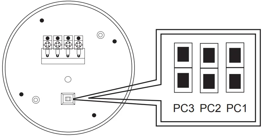
| Tone Selection | PC3 Pattern | PC2 Tone | PC1 Volume | |
| Jumper |  | Non- Temporal | Electro- Mechanical | High |
 | Temporal | 3000Hz | Low | |
| Strobe Light Only | Max. RMS operating Current (mA) | |
| Regulated 24V DC (Typical) | Regulated 24V FWR (Typical) | |
| 30cd | 121 (88) | 169 (124) |
| 75cd | 178 (128) | 244 (178) |
| 110cd | 242 (166) | 304 (226) |
![]() WARNING
WARNING
Strobes must be used only on circuits with continuously operating voltage.
DO NOT use strobe on coded or interrupted circuits in which the applied voltage is interrupted ON and OFF as the strobe may fail to flash.
The applied voltage must be within its rated input voltage range.
Fuse ratings on signaling circuits must handle peak currents from all devices connected to those circuits.
| Horn Only Current Draw and Output Table | PC3: Pattern PC2: Tone PC1: Volume | Max. RMS Operating Current (mA) | Min. sound Output (dBA @ 10ft. per UL 464) | |||||
| PC3 | PC2 | PC1 | Regulated 24V DC | Regulated 24V FWR | Regulated 24V DC | |||
| Non-Temporal | Electro- Mechanical | HIGH | 1 | 1 | 1 | 49 | 45 | 86 |
| LOW | 1 | 1 | 0 | 34 | 34 | 76 | ||
| 3000 Hz | HIGH | 1 | 0 | 1 | 49 | 45 | 87 | |
| LOW | 1 | 0 | 0 | 34 | 34 | 77 | ||
| Temporal | Electro- Mechanical | HIGH | 0 | 1 | 1 | 49 | 45 | 80 |
| LOW | 0 | 1 | 0 | 34 | 34 | 73 | ||
| 3000 Hz | HIGH | 0 | 0 | 1 | 49 | 45 | 82 | |
| LOW | 0 | 0 | 0 | 34 | 34 | 74 | ||
Optional Mounting (using SPC-1 retrofit plate)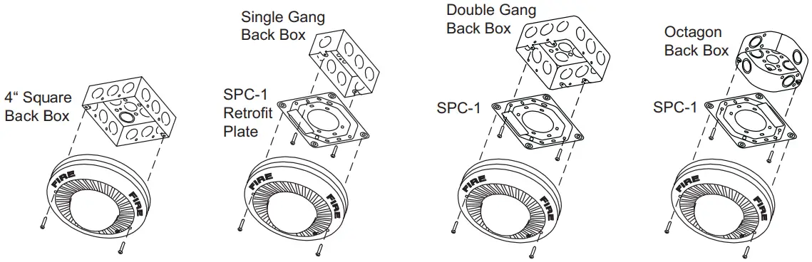
Optional Surface Mounting (using RBX-1 back box skirt and SPC-1 retrofit plate)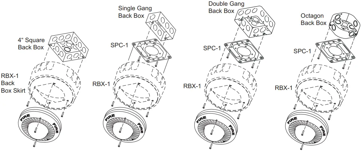
CUSTOMER SUPPORT
Potter Electric Signal Co., LLC
St. Louis, MO
Cust Service: 866-240-1870
Tech Support: 866-956-1211
Canada: 888-882-1833
Web: www.pottersignal.com