POTTER CSH24W Series Wall Mount Colored Horn Strobe
Introduction
- Limitless applications: Weather warning, mass notification, leaks, etc.
- Selectable candela output
- NFPA/ANSI compliant
- UL listed for wall mounting
- Polarized strobes with wide operating voltage range using filtered
- DC or unfiltered FWR input voltage
- Horn field selectable tones: 3000 Hz interrupted or electro-mechanical
- Temporal or Non-temporal
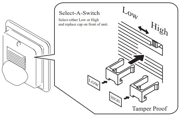
- High or low-ball output
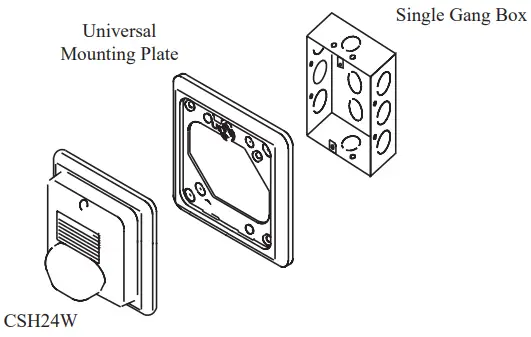
- Universal mounting plate for 4”, single gang back box and more
- Synchronization using Sync Module (SMD10-3A)
- Available in red or white housing
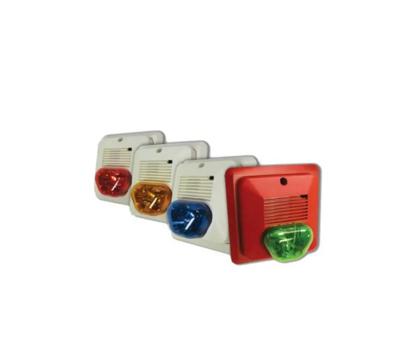
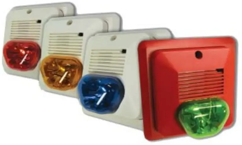
- Available strobe colors: amber, blue, green, red
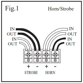
The Amseco Colored Strobe utilizes a patented design that produces a true color output. The CSH24W offer a slim-line look with a stylish round strobe. The CSH24W colored strobe/horns are UL listed for indoor applications. The terminal strips accept a wide cable offering and provide a simple connection of one or multiple devices. The strobe/horn combinations are selectable with either a continuous or ANSI Temporal 3 output.
These strobes are used in various applications such as Mass Notifi cation, Severe Weather Warning, Machine Operation, Industrial Detection Systems, Access Control and many, many more. These devices are UL listed for general signaling (UL 1638) and comply with the requirements for signaling of the hearing impaired (UL 1971). The bodies of the strobes are available in red or white. The strobes are designed for 24 VDC, however will operate anywhere between 16 and 33 VDC.
Ordering Information
Model Number | Stock Number | Housing Color | Strobe Color | Input Voltage | Strobe Candela | Mounting Type | Light Output | Flash Rate | Operating Temperature Range |
CSH24W-AW | 4800002 | White | Amber | Regulated 24V DC/ FWR | 75/145 | Wall Mount | Low/High | 60 times/ minute | 32°F – 120°F (0°C – 49°C) |
| CSH24W-BW | 4800004 | Blue | 40/79 | ||||||
CSH24W-GW | 4800006 | Green | 79/154 | ||||||
| CSH24W-RW | 4800008 | Red | 35/68 | ||||||
| CSH24W-AR * | 4800001 |
Red | Amber | 75/145 | |||||
CSH24W-BR | 4800003 | Blue | 40/79 | ||||||
| CSH24W-GR * | 4800005 | Green | 79/154 | ||||||
CSH24W-RR | 4800007 | Red | 35/68 |
*Contact Potter before ordering
Engineering Specifi cations
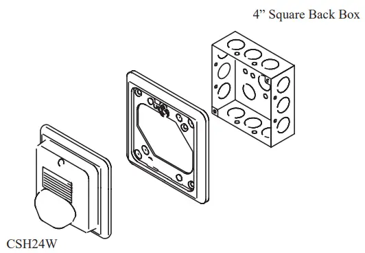
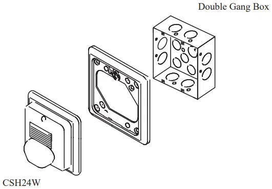
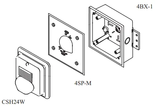
The Amseco CSH24W colored strobe/horn shall be provided for visual and audible notification. The device shall have a universal mounting plate and connect to a single gang, double gang, four inch square or octagon box. The devices shall be UL listed for General Signaling and shall comply with light output requirements of UL 1971 for spacing. The colored strobes shall have a minimum light output of 15 cd. The reflective mirror shall be the same color as the lens to produce a true color of amber, red, blue or green. The strobe shall operate between 16 and 33 VDC regulated or full wave rectified. The strobe shall fl ash a minimum of once a second continuously at 16 VDC.
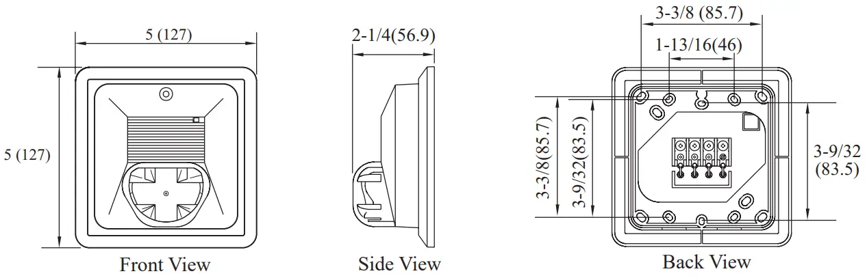
Dimensions: inches (mm)
Specifications
Light Output Dispersion | Light Output on Axis (cd) | |
| Low | High | |
Amber | 75 | 145 |
| Blue | 40 | 79 |
Green | 79 | 154 |
| Red | 35 | 68 |
White | 27 | 53 |
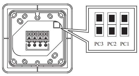
| Tone Selection | PC3 Pattern | PC2 Tone | PC1 Volume | |
| Jumper |  | Non- Temporal | Electro- Mechanical | High |
|
| Temporal | 3000Hz | Low | |

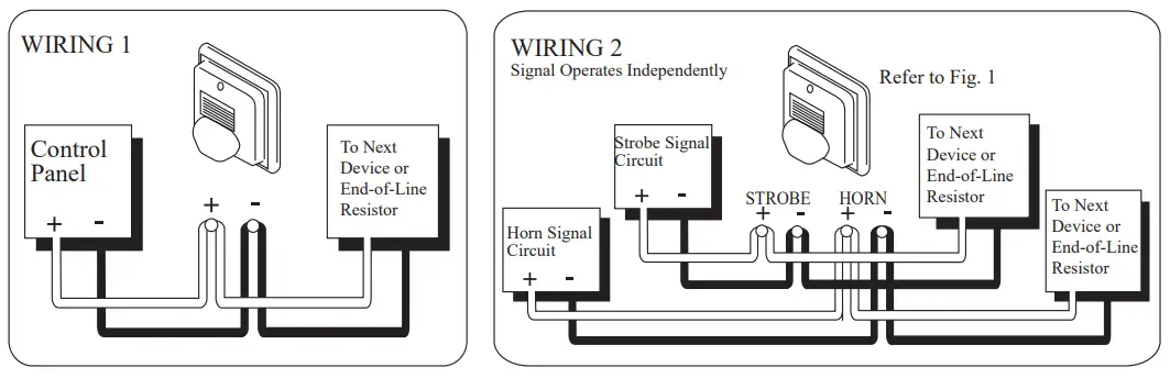
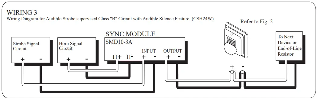
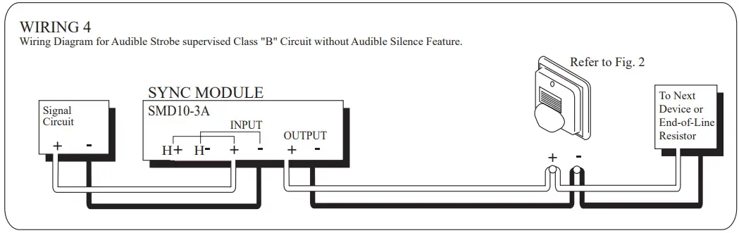
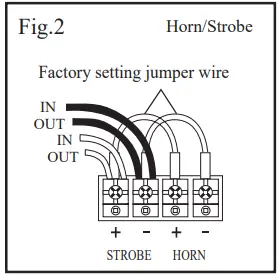
Wiring Diagram
| Strobe Light Only | Max. RMS operating Current (mA) | |
| Regulated 24V DC (Typical) | Regulated 24V FWR (Typical) | |
| 15cd | 88 (57) | 127 (95) |
| 30cd | 134 (87) | 184 (135) |
| Under ULC 525/526 | ULC Current @ 24V DC (mA) | |
| Low Volume | High Volume | |
| 15cd | 79 | 92 |
| 30cd | 111 | 124 |
![]() WARNING
WARNING
The strobe/horn must be used only on circuits with continuously operating voltage. DO NOT use strobe on coded or interrupted circuits in which the applied voltage is interrupted ON and OFF as the strobe may fail to fl ash. The applied voltage must be within its rated input voltage range. Fuse ratings on signaling circuits must handle peak currents from all devices connected to those circuits
Strobe/Horn Current Draw Table | PC3: Pattern PC2: Tone PC1: Volume | Maximum RMS Operating Current (mA) | Minimum Sound Output (dBA at 10ft per UL464) | ||||||
| PC3 | PC2 | PC1 | Regulated 24V DC (Typical) | Regulated 24V FWR (Typical) | Regulated 24V DC | ||||
| Horn & Strobe (Low) | Non-Temporal | Electro Mecanical | HIGH | 1 | 1 | 1 | 112 (99) | 145 (145) | 83 |
| 3000 Hz | LOW | 1 | 1 | 0 | 109 (80) | 142 (120) | 74 | ||
| Electro Mechanical | HIGH | 1 | 0 | 1 | 118 (99) | 153 (145) | 84 | ||
| 3000 Hz | LOW | 1 | 0 | 0 | 106 (80) | 139 (120) | 74 | ||
| Temporal | Electro Mechanical | HIGH | 0 | 1 | 1 | 112 (99) | 145 (145) | 79 | |
| LOW | 0 | 1 | 0 | 109 (80) | 142 (120) | 69 | |||
| 3000 Hz | HIGH | 0 | 0 | 1 | 118 (99) | 153 (145) | 80 | ||
| LOW | 0 | 0 | 0 | 106 (80) | 139 (120) | 70 | |||
| Horn & Strobe (High) | Non-Temporal | Electro Mechanical | HIGH | 1 | 1 | 1 | 158 (130) | 207 (185) | 83 |
| LOW | 1 | 1 | 0 | 155 (111) | 204 (160) | 74 | |||
| 3000 Hz | HIGH | 1 | 0 | 1 | 164 (130) | 215 (185) | 84 | ||
| LOW | 1 | 0 | 0 | 152 (111) | 201 (160) | 74 | |||
| Temporal | Electro Mechanical | HIGH | 0 | 1 | 1 | 158 (130) | 207 (185) | 79 | |
| LOW | 0 | 1 | 0 | 155 (111) | 204 (160) | 69 | |||
| 3000 Hz | HIGH | 0 | 0 | 1 | 164 (130) | 215 (185) | 80 | ||
| LOW | 0 | 0 | 0 | 152 (111) | 201 (160) | 70 | |||
| Horn Only | Non-Temporal | Electro Mechanical | HIGH | 1 | 1 | 1 | 57 | 91 | 83 |
| LOW | 1 | 1 | 0 | 42 | 44 | 74 | |||
| 3000 Hz | HIGH | 1 | 0 | 1 | 70 | 68 | 84 | ||
| LOW | 1 | 0 | 0 | 36 | 38 | 74 | |||
| Temporal | Electro Mechanical | HIGH | 0 | 1 | 1 | 57 | 91 | 79 | |
| LOW | 0 | 1 | 0 | 42 | 44 | 69 | |||
| 3000 Hz | HIGH | 0 | 0 | 1 | 70 | 68 | 80 | ||
| LOW | 0 | 0 | 0 | 36 | 38 | 70 | |||
| Sound Output Dispersion | Horizontal dB | Vertical dB | |||
| Strobe/ Horn | Horn Only | Strobe/ Horn | Horn Only | ||
| DEGREES | +90 | -6 | -6 | -3 | -3 |
| +60 | -2 | -2 | -2 | -2 | |
+30 | -1 | -1 | -1 | -1 | |
| 0 | 0 | 0 | 0 | 0 | |
-30 | -1 | -1 | -3 | -1 | |
| -60 | -2 | -2 | -5 | -3 | |
-90 | -6 | -6 | -6 | -4 | |
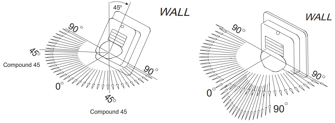
Installation Options
Customer Support
Potter Electric Signal Company
2081 Craig Road, St. Louis, MO, 63146-4161
Phone: 800-325-3936/Canada 888-882-1833
www.pottersignal.com
firealarmresources.com