
Mircom FHS-400 Wall Mount LED Horn or Strobes
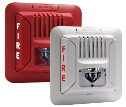
WALL MOUNT LED HORN/STROBES
FHS-400
Description
- Mircom’s FHS-400 wall mount horn/strobes offer an audible/visual solution that delivers exceptional energy efficiency in a compact design. Utilizing advanced
- LED technology, the FHS-400 LED horn/strobes provide a lower current draw which allows for more devices on a NAC circuit while reducing the number of external power supplies required.
- The FHS-400 horn/strobes offer a wide range of audible/visual settings in a single compact device. The audible settings include Temporal, Continuous, March
- Time and 20 BPM tones that can each be set for Low or High volume settings. The candela settings can be field-configured for 15, 15/75, 30, 75, 110, 185 cd.
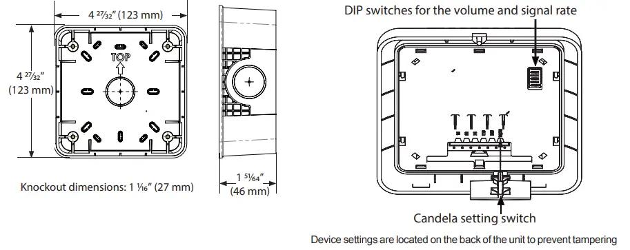
- The candela setting is displayed through the front window for easy identification All device settings are located on the back of the unit to prevent tampering.
- The FHS-400 horn/strobes can be synchronized using a control panel with the Mircom sync protocol or the SDM-240 synchronization module.
- The FHS-400 horn/strobes utilize a universal mounting plate that allows for mounting to a single gang, double gang, octagon, 4” junction or 4” square electrical box. The back plate allows the installer to mount the plate and connect the wire connections. The device attaches to the mounting plate and is secured by a single mounting screw. In addition, the FHS-400 can mount to the Mircom BB-400 Series back box for surface mount applications.
Features
- Compact Design
- Advanced LED technology provides superior current draw performance
- Lower power consumption per device allows for more notification appliances per circuit and reduces the need for external power supplies
- Standard and High candela settings in one unit to meet virtually any application
- 15, 15/75, 30, 75, 110, 185 cd
- Multiple field-selectable audible settings
- Temporal, Continuous, March Time and 20 BPM audible tones
- High and Low volume settings
- Red or white finish
- Device settings are located on the back of the unit to prevent tampering
- Includes shorting clip that allows installers to test the wiring before the device is installed
- Supports 12 to 22 AWG
- Mount to Mircom BB-400 surface mount back box, single gang, 4-inch square, double gang, octagon and 4-inch junction boxes
- All units include universal mounting plate
- For indoor applications
Compliance
- UL 1971
- UL 1638
- UL 464
- ULC-S525
- ULC-S526
- NFPA 72 2016 Edition
Engineering Specifications
The horn/strobe shall be a Mircom FHS-400 notification appliance for wall mount applications. The horn/strobe shall be of a low current draw design and operate at 24 VDC regulated or full wave rectified. The horn/strobe shall have two field selectable volume settings and a choice of four tone settings for temporal, continuous, march time or 20 BPM. The horn/strobe shall incorporate a Light Emitting Diode (LED) as the light source and have six field selectable settings of 15, 15/75, 30, 75, 110, 185 candela. The candela settings shall show the candela selection in a visible location at all times when installed. Both the audible and candela settings shall be tamper resistant. The horn/strobe shall be synchronized using a control panel with the Mircom sync protocol or the SDM-240 sync module. The horn/strobe shall utilize a mounting plate that allows the installer to pre-wire the mounting plate. The mounting plate shall mount on a single gang, double gang, octagon, 4-inch square box or Mircom’s BB-400 series back box. The horn/strobe shall be listed to UL standard 464, Audible Signaling Devices for Fire Alarm and Signaling Devices, UL standard 1638, Visible Signaling Devices for Fire Alarm and Signaling Systems and standard 1971, Signaling Devices for the Hearing Impaired. In addition, the horn/strobe shall be listed to ULC-S525, Audible Signal Devices for Fire Alarm Systems and ULC S526, Visible Signal Devices for Fire Alarm Systems.
FHS-400 Dimensions
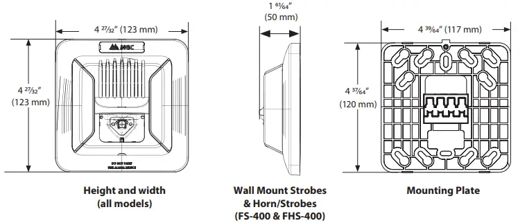
- BB-400 Dimensions
- Audible/Visual Settings

Specifications
General Specifications
| Operating temperature | 0°C to 50°C (32°F to 122°F) |
| Humidity range | 0% to 93% |
| Strobe flash rate | 1 Hz |
| Nominal Voltage | Regulated 24 VDC / 24 VFWR |
| Operating Voltage Range (RMS) | 16 to 33 |
| Input terminal wire gauge | 22 AWG to 12 AWG |
| Installation environment | For indoor use only |
FHS-400 Wall Horn/Strobe Operating RMS Currents (mA)
|
Candela | Regulated 24 VDC | Regulated 24 VFWR | ||
| Temporal Tone, High Volume* | Continuous Tone, High Volume | Temporal Tone, High Volume* | Continuous Tone, High Volume | |
| 15 | 30 | 47 | 69 | 73 |
| 30 | 44 | 53 | 99 | 102 |
| 75 | 103 | 106 | 189 | 194 |
| 15/75 | 107 | 97 | 190 | 196 |
| 110 | 107 | 111 | 190 | 199 |
| 185 | 180 | 183 | 236 | 243 |
Audible Ratings
dBA Reverberant Ratings per UL464 (dBA@10 ft)
| Sound Pattern | Volume | 16 VDC | Reg. 24 VDC | 33 VDC | 16 FWR | Reg. 24 FWR | 33 FWR |
| Temporal | High | 82.2 | 84.9 | 84.6 | 76.8 | 79 | 80 |
| Low | 75.5 | 80.5 | 80.2 | 71.8 | 75.1 | 76.6 | |
| Continuous | High | 86.4 | 89.2 | 88.7 | 81.5 | 83.1 | 84 |
| Low | 79.9 | 84 | 84.8 | 76.2 | 79.3 | 81.2 | |
| 20 BPM | High | 79 | 81.3 | 81.6 | 74 | 75.1 | 76.1 |
| Low | 72.3 | 76 | 76.7 | 68.9 | 71.7 | 73.3 | |
| March | High | 83.2 | 86.4 | 85.7 | 79.2 | 80.6 | 81.4 |
| Low | 76.9 | 80.9 | 81.7 | 73.3 | 76.2 | 78 |
dBA Anechoic Ratings per CAN/ULC-S525 (dBA@3 m)
| Sound Pattern | Volume | 16 VDC | Reg. 24 VDC | 33 VDC | 16 FWR | Reg. 24 FWR | 33 FWR |
| Temporal | High | 90.2 | 93.2 | 93.2 | 84.4 | 87.1 | 88.5 |
| Low | 83.7 | 87.4 | 88.3 | 78 | 82.2 | 84.5 | |
| Continuous | High | 90.2 | 93.2 | 93.3 | 85.1 | 87.8 | 89 |
| Low | 83.8 | 87.6 | 88.6 | 78.5 | 83 | 85 | |
| 20 BPM | High | 90.3 | 92.9 | 92.9 | 84.4 | 87.2 | 88.6 |
| Low | 83.6 | 87.3 | 88.3 | 78 | 82.2 | 84.5 | |
| March | High | 90.2 | 92.9 | 92.9 | 84.4 | 87.1 | 88.4 |
| Low | 83.7 | 87.4 | 88.3 | 78 | 82.2 | 84.4 |
ULC Directional Sound Characteristics
| Horizontal Axis | |
| ± 45° | -3 dbA |
| ± 61° | -6 dbA |
| ± 90° | -10 dbA |
| Vertical Axis | |
| ± 49° | -3 dbA |
| ± 61° | -6 dbA |
| ± 90° | -7.7 dbA |
Light Output Dispersion
| Degrees | % of Candela Rating | |
| Horizontal Dispersion | Vertical Dispersion, Wall to Floor | |
| ±0 | 149 | 148 |
| ±5 | 146 | 149 |
| ±10 | 143 | 153 |
| ±15 | 138 | 135 |
| ±20 | 134 | 104 |
| ±25 | 128 | 101 |
| ±30 | 123 | 94 |
| ±35 | 116 | 92 |
| ±40 | 106 | 84 |
| ±45 | 99 | 75 |
| ±50 | 92 | 68 |
| ±55 | 87 | 65 |
| ±60 | 82 | 61 |
| ±65 | 78 | 58 |
| ±70 | 75 | 54 |
| ±75 | 73 | 49 |
| ±80 | 72 | 43 |
| ±85 | 81 | 40 |
| ±90 | 53 | 30 |
| Compound ±45° | 42 | |
Note: The values are shown as percentages of the rated light output at any candela setting.
Ordering Information
| Model Number | Description |
| FHS-400-RR | Wall Mount Horn/Strobe, Red |
| FHS-400-WW | Wall Mount Horn/Strobe, White |
| BB-400R | Surface Mount Back Box, Red |
| BB-400W | Surface Mount Back Box, White |
| SDM-240 | Synchronization Module |
Canada
25 Interchange Way Vaughan, Ontario L4K 5W3 Telephone: (905) 660-4655 Fax: (905) 660-4113
Web page: http://www.mircom.com
U.S.A.
4575 Witmer Industrial Estates Niagara Falls, NY 14305
Toll Free: (888) 660-4655 Fax Toll Free: (888) 660-4113
Email: [email protected]

 Mircom reserves the right to make changes at any time without notice in prices, colours, materials, components, equipment, specifications and models and also to discontinue models


