![]() WALL/CEILING MOUNT HORNS
WALL/CEILING MOUNT HORNS
FH-400
CATALOG NUMBER-5273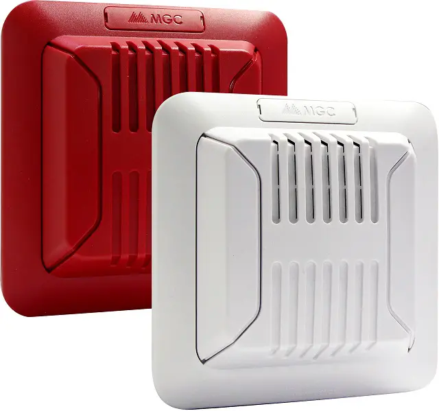
Description
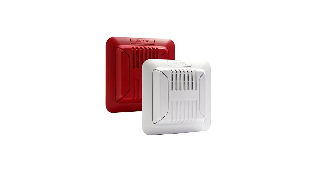
Mircom’s FH-400 Horns offer an audible solution that deliver exceptional energy efficiency in a compact design. The FH-400 Series Horns provide a wide range of audible settings in a single compact device. The audible settings include Temporal, Continuous, March Time and 20 BPM tones that can each be set for Low or High volume settings. The device settings are located on the back of the unit to prevent tampering.
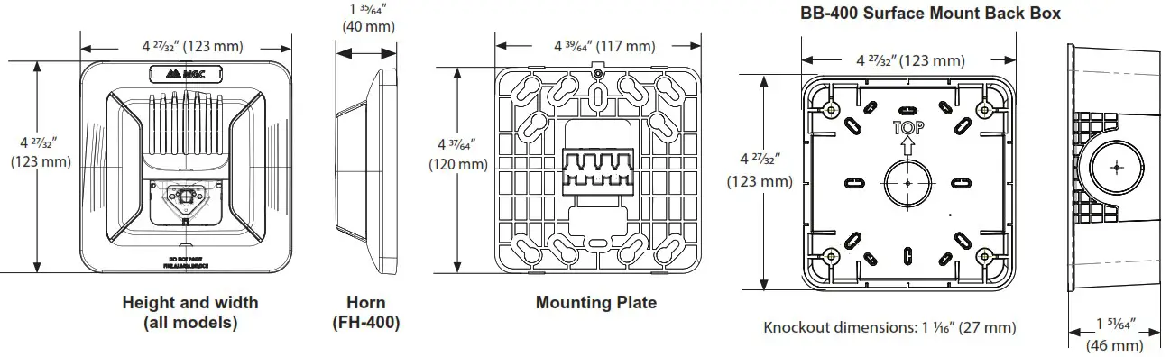
The FH-400 Series Horns utilize a universal mounting plate that allows for mounting to a single gang, double gang, octagon, 4″ junction or 4″ square electrical box. The back plate allows the installer to mount the plate and connect the wire connections. The device attaches to the mounting plate and is secured by a single mounting screw. In addition, the FH-400 can mount to the Mircom BB-400 Series back box for surface mount applications.
Engineering Specifications
The horn shall be a Mircom FH-400 audible appliance for wall or ceiling mount applications. The horn shall be of a low current draw design and operate at 24 VDC regulated or full wave rectified. The horn shall have two field selectable volume settings and a choice of four tone settings for temporal, continuous, march time or 20 BPM. The audible settings shall be tamper resistant. The horn shall utilize a mounting plate that allows the installer to prewire the mounting plate. The mounting plate shall mount on a single gang, double gang, octagon, 4-inch square box or Mircom’s BB-400 series back box. The horn shall be listed to UL standard 464, Audible Signaling Devices for Fire Alarm and Signaling Devices and ULC-S525, Audible Signal Devices for Fire Alarm Systems.
Features
- Compact Design
- Lower power consumption per device allows for more notification appliances per circuit and reduces the need for external power supplies
- Multiple field-selectable audible settings
- Temporal, Continuous, March Time and 20 BPM audible tones
- High and Low volume settings
- Wall and ceiling-mount
- Red or white finish
- Device settings are located on the back of the unit to prevent tampering
- Includes shorting clip that allows installers to test the wiring before the device is installed
- Supports 12 to 22 AWG
- Mount to Mircom BB-400 surface mount back box, single gang, 4-inch square, double gang, octagon and 4-inch junction boxes
- All units include universal mounting plate
- For indoor applications
Compliance
- UL 464
- ULC-S525
Audible Settings
DIP switches for the audible tone and volume settings
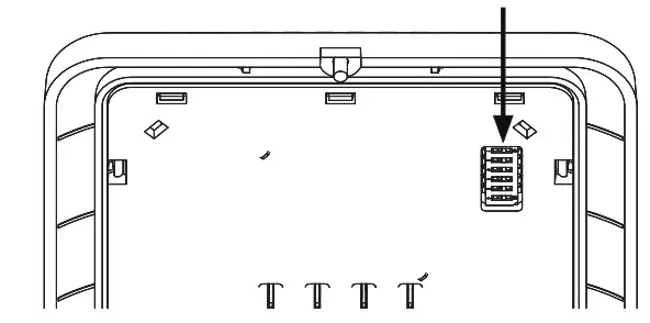 Device settings are located on the back of the unit to prevent tampering
![]()
Specifications
General Specifications
| Operating temperature | 0°C to 50°C (32°F to 122°F) |
| Humidity range | 0% to 93% |
| Nominal Voltage | Regulated 24 VDC / 24 VFWR |
| Operating Voltage Range (RMS) | 16 to 33 |
| Input terminal wire gauge | 22 AWG to 12 AWG |
| Installation environment | For indoor use only |
FH-400 Horn Operating RMS Currents (mA)
| Volume | Reg. 24 VDC, all tones | Reg. 24 VFWR, all tones |
| High | 37 | 31 |
| Low | 22 | 25 |
ULC Directional Sound Characteristics
| Horizontal Axis | |
| ± 45° | -3 dbA |
| ± 61° | -6 dbA |
| ± 90° | -10 dbA |
| Vertical Axis | |
| ± 49° | -3 dbA |
| ± 61° | -6 dbA |
| ± 90° | -7.7 dbA |
Audible Ratings
FH-400 Horn Operating RMS Currents (mA)
| Sound Pattern | Volume | 16 VDC | Reg. 24 VDC | 33 VDC | 16 FWR | Reg. 24 FWR | 33 FWR |
| Temporal | High | 82.2 | 84.9 | 84.6 | 76.8 | 79 | 80 |
| Low | 75.5 | 80.5 | 80.2 | 71.8 | 75.1 | 76.6 | |
| Continuous | High | 86.4 | 89.2 | 88.7 | 81.5 | 83.1 | 84 |
| Low | 79.9 | 84 | 84.8 | 76.2 | 79.3 | 81.2 | |
| 20 BPM | High | 79 | 81.3 | 81.6 | 74 | 75.1 | 76.1 |
| Low | 72.3 | 76 | 76.7 | 68.9 | 71.7 | 73.3 | |
| March | High | 83.2 | 86.4 | 85.7 | 79.2 | 80.6 | 81.4 |
| Low | 76.9 | 80.9 | 81.7 | 73.3 | 76.2 | 78 |
dBA Anechoic Ratings per CAN/ULC-S525 (dBA@3 m)
| Sound Pattern | Volume | 16 VDC | Reg. 24VDC | 33 VDC | 16 FWR | Reg. 24FWR | 33 FWR |
| Temporal | High | 90.2 | 93.2 | 93.2 | 84.4 | 87.1 | 88.5 |
| Low | 83.7 | 87.4 | 88.3 | 78 | 82.2 | 84.5 | |
| Continuous | High | 90.2 | 93.2 | 93.3 | 85.1 | 87.8 | 89 |
| Low | 83.8 | 87.6 | 88.6 | 78.5 | 83 | 85 | |
| 20 BPM | High | 90.3 | 92.9 | 92.9 | 84.4 | 87.2 | 88.6 |
| Low | 83.6 | 87.3 | 88.3 | 78 | 82.2 | 84.5 | |
| March | High | 90.2 | 92.9 | 92.9 | 84.4 | 87.1 | 88.4 |
| Low | 83.7 | 87.4 | 88.3 | 78 | 82.2 | 84.4 |
Dimensions
Ordering Information
| Model Number | Description |
| FH-400-RR | Wall/Ceiling Mount Horn, Red |
| FH-400-WW | Wall/Ceiling Mount Horn, White |
| BB-400R | Surface Mount Back Box, Red |
| BB-400W | Surface Mount Back Box, White |
| SDM-240 | Synchronization Module |
![]()
Canada | U.S.A. |
NOT TO BE USED FOR INSTALLATION PURPOSES. Distributed by:
ISO 9001:2008
REGISTERED![]() CAT. 5273 Rev.1
CAT. 5273 Rev.1
firealarmresources.com


