![]()
INSTALLATION INSTRUCTIONS
FOR OUTDOOR HORNS
REVISION DATE: 05-14-2021
PART#: 98-0020-01
Caution:
- Water Ingress: No additional penetrations may be created in the product unless they are sealed per Nema 4 Standard. All field penetrations must be tested using a stream of water poured from a container located not less than 6” away horizontally. Warranty will be void if this testing is not completed during installation, or if there is water ingress from field modifications. Any cabinets located above the product must not allow water to build up and then flow through conduits into the product. Penetrations between product and higher cabinets must be sealed between the cabinet internal spaces using a water-tight cable to conduit seals. Holes remaining from eyebolt removal must be filled, sealed, and tested.
- Ventilation: Install the product so that airflow is not restricted. The customer’s structure must allow for the free flow of outside ambient air to the product, without recirculation of air. Warranty will be void if components fail due to airflow restrictions.
Follow these instructions when installing a #55 Federal horn (Horn Kit #01-0000-01):
- The scoreboard will have an access door on the back near the horn location or a removable socket plate assembly on the right side of the scoreboard. The socket plate will be attached with #6 sheet metal screws, not rivets (a 1/4” nut driver will be required to remove screws). The removable socket plate will be either visitor score or ball possession (depending on the model scoreboard).
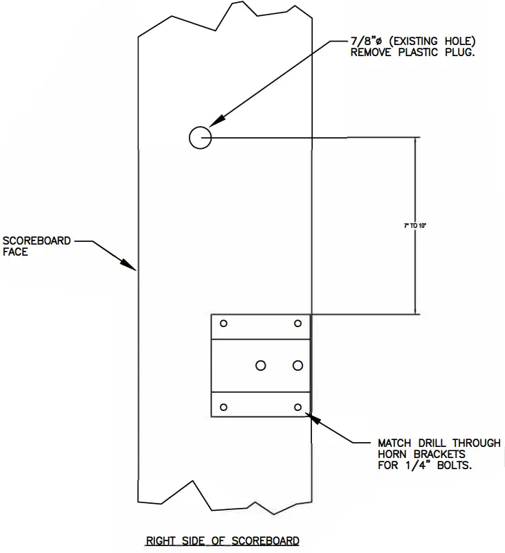
- Remove plastic plug on the right end of the scoreboard, match drill, and mount the horn mounting bracket from 7” to 10” below the 7/8” dia. hole, using the ¼” hardware provided. See print #01-0000-01.
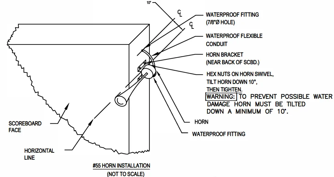
- Attach horn to the mounting bracket with 3/8” hardware provided. Make sure the horn is pointed down approximately 10 degrees. WARNING: TO PREVENT WATER DAMAGE HORN MUST BE TILTED DOWN A MINIMUM OF 10 DEGREES.
- Insert the wire harness and attach the flexible conduit from the horn to the 7/8” dia. hole provided. Attach conduit lock nut securely from the inside of the cabinet.
- Inside the cabinet behind the socket plate assembly, you may find an optional connector, if no connector, skip stepping
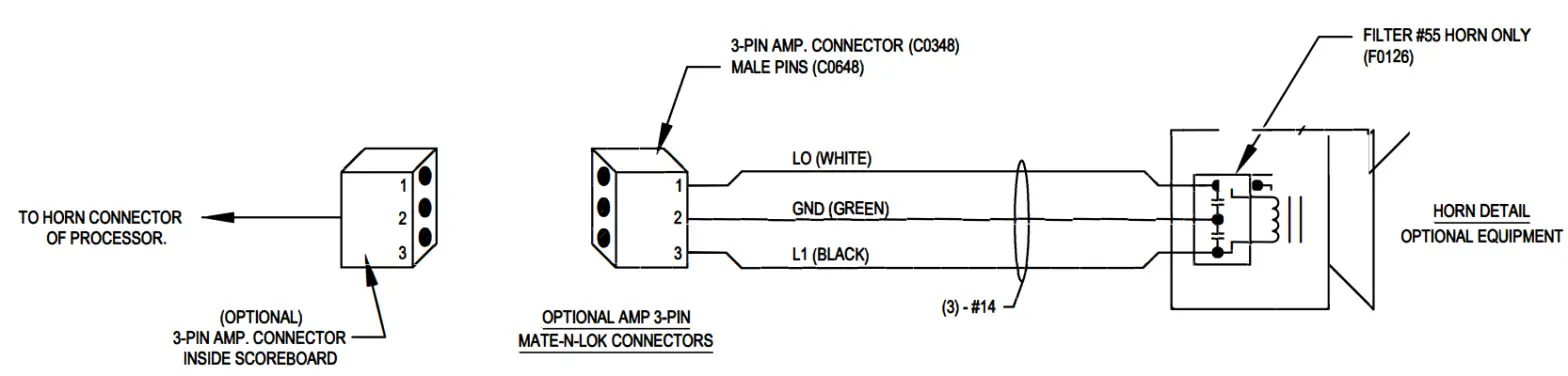
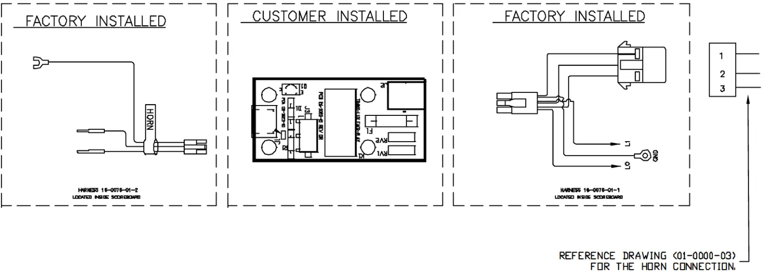
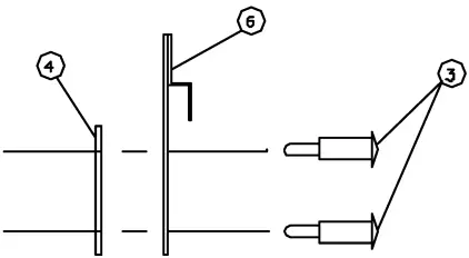
- If your scoreboard has a three-pin connector, pin connector according to drawing number 01-0000-03 and plug connectors together securely.
- If there is no connector you will find 3 wires (white, black & green). Using twist nuts provided splice white, black, and green wires from horn to these three wires matching color to color.
- Re-install socket plate assembly.
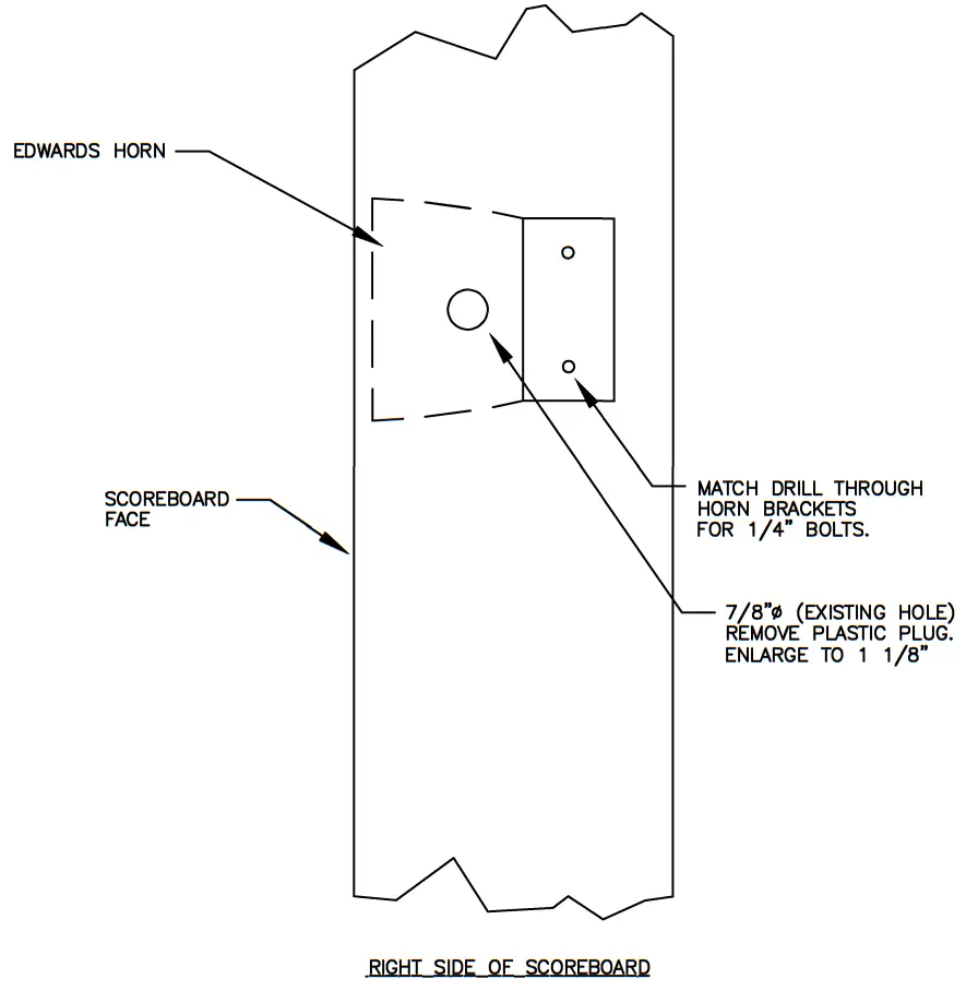
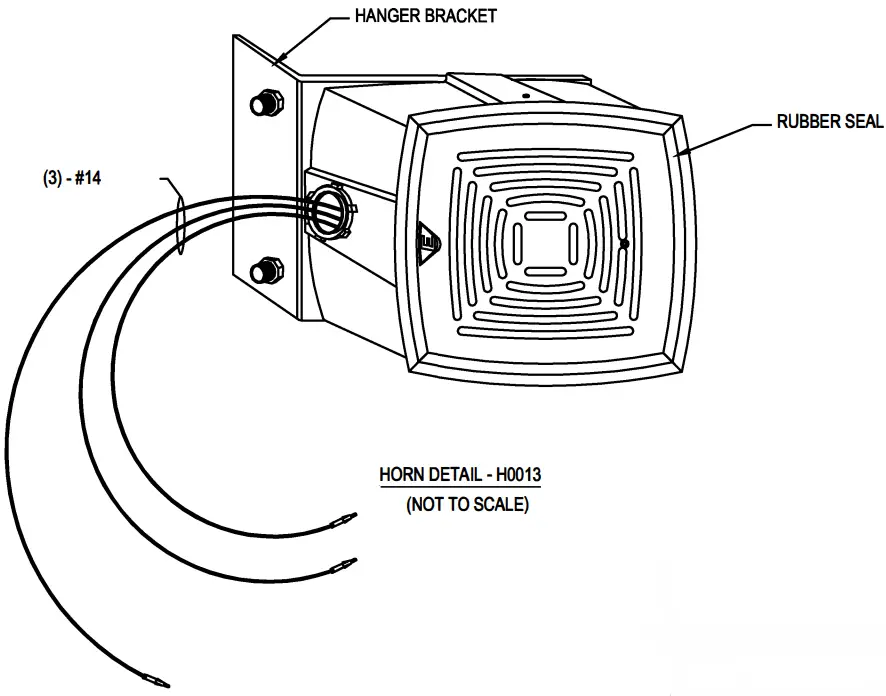
Follow these instructions when installing a #876-N5 Edwards horn (Horn Kit #01-0000-02):
- The scoreboard will have an access door on the back near the horn location or a removable socket plate assembly on the right side of the scoreboard. The socket plate will be attached with #6 sheet metal screws, not rivets (a 1/4” nut driver will be required to remove screws). The removable socket plate will be either visitor score or ball possession (depending on the model scoreboard).
- Remove the plastic plug, enlarge the 7/8”dia. hole to 1 1/8” dia., or drill a 1 1/8”dia. hole close to the 7/8” dia. Reference drawing number 01-0000-02 for location. Insert wiring harness and attach horn using conduit lock nut provided.
- Match drill horn mounting plate to the scoreboard and attach using ¼” hardware provided.
- Inside the cabinet behind the socket plate assembly, you may find an optional connector, if no connector skip stepping
- If your scoreboard has a three-pin connector, pin connector according to drawing number 01-0000-03 and plug connectors together securely.
- If there is no connector you will find 3 wires (white, black & green). Using twist nuts provided splice white, black, and green wires from horn to these three wires matching color to color.
- Re-install socket plate assembly.
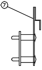
Follow these instructions when installing optional Horn driver (Horn kit #01-0000-06-1 & 01-0000-06-2)
- This installation will require working with 120vac; Seeking the services of a qualified licensed electrician. Warning electric shock is possible which may result in injury or even death if not installed properly.
- Disconnect all power sources to the scoreboard prior to installing the horn driver and horn to your scoreboard.
- Facing the front side of the scoreboard, locate the access door, some scoreboards will have more than one door, you will need to locate the top or uppermost door.
- When you open the door you will see a sheet metal enclosure. Loosen the two screws on the cover face, slide the cover plate up, pull out past the retaining screws, and pull down, to remove this cover.
- Inside the enclosure, you will see the scoreboard driver assembly (LED-1208), and the wireless receiver 16-0006-07, (if supplied with your scoreboard). There will be a metal bracket located above the driver assembly which mates with the horn driver (16-0006-05) supplied in the horn kit. Simply hang the horn driver on this metal bracket for attachment.
- Referencing drawing 01-0000-06 for wiring details. Inside the scoreboard driver enclosure, there will be a white plug with black, white, and green wires, and a black plug with red and purple wires. On the horn driver, you will see corresponding white and black receptacles. . Double check to ensure the power source is disconnected and attach the plugs accordingly. Recheck to ensure all wires are properly attached and routed to ensure no damage will occur for your safety and for all equipment installed.
- Next, install the horn by referencing drawings 01-0000-01 or 01-0000-02.
- Reconnect power to the scoreboard, and check operation. If the operation is correct jump to step ten. If the horn does not function properly turn off the power and recheck all connections. If connections are correct, contact an authorized Fair-Play service dealer nearest you or contact the service center at (800) 462-2716 for additional assistance.
- Attach all covers securely, and close the access door.
01-0000-06-1 Horn kit includes:
16-0006-05-Horn relay card assembly
98-0020-01-Instructions
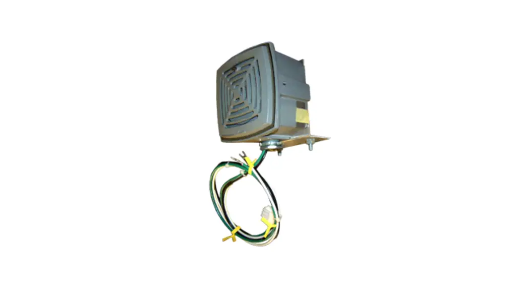
#55 Horn (H0001) and mounting hardware
01-0000-06-2 Horn kit includes:
16-0006-05-Horn relay card assembly
98-0020-01-Instructions
#867-NS Horn (H0013) and mounting hardware
Required tools: Standard blade screwdriver, 1/4” nut driver, ratchet, 9/16 socket, 7/16 socket, and Channel locks.
| ITEM | CHANGE | DATE | BY |
| THIS DOCUMENT CONTAINS FAIR-PLAY PROPRIETARY INFORMATION. ANY DISCLOSURE, USE, OR DUPLICATION OF THE DOCUMENT OR OF ANY INFORMATION CONTAINED THEREIN FOR OTHER THAN THE SPECIFIC PURPOSE FOR WHICH IT WAS DISCLOSED IS EXPRESSLY PROHIBITED, EXCEPT AS MAY BE OTHERWISE AGREED TO IN WRITING | |||
| TITLE DETAIL FOR | DRAWN BY BEW | A | MODEL: | |
| DATE 08-04-98 | DWG. No. 01 -0000-03 | |||
| SCALE NONE | ||||
| ITEM | CHANGE | DATE | BY |
HAZELWOOD, MO 63042 fair-play.corn | THIS DOCUMENT CONTAINS FAIR-PLAY PROPRIETARY INFORMATION. ANY DISCLOSURE, USE, OR DUPLICATION OF THE DOCUMENT OR OF ANY INFORMATION CONTAINED THEREIN FOR OTHER THAN THE SPECIFIC PURPOSE FOR WHICH IT WAS DISCLOSED IS EXPRESSLY PROHIBITED, EXCEPT AS MAY BE OTHERWISE AGREED TO IN WRITING | |||
| TITLE INSTALLATION DETAIL FOR OUTDOOR SCOREBOARD FEDERAL #55 HORN | DRAWN BY BEW | A | MODEL: COMMON | |
| DATE 07-14-98 | DWG. No. 01-0000-01 | |||
| SCALE 1/4″=1″ | ||||
| ITEM | CHANGE | DATE | BY |
HAZELWOOD, MO 63042 fair-play.corn | THIS DOCUMENT CONTAINS FAIR-PLAY PROPRIETARY INFORMATION. ANY DISCLOSURE, USE, OR DUPLICATION OF THE DOCUMENT OR OF ANY INFORMATION CONTAINED THEREIN FOR OTHER THAN THE SPECIFIC PURPOSE FOR WHICH IT WAS DISCLOSED IS EXPRESSLY PROHIBITED, EXCEPT AS MAY BE OTHERWISE AGREED TO IN WRITING | |||
| TITLE DETAIL FOR OUTDOOR SCOREBOARD #876-N5 EDWARDS HORN | DRAWN BY BEW | A | MODEL: #876-N5 | |
| DATE 08-10-98 | DWG. No. 01-0000-02 | |||
| SCALE 1/4″=1″ | ||||
EXPLODED VIEW
SIDE VIEW
HANG ON JOGGLE IS AVAILABLE IN51DE DRIVER ENCLOSER
WIRING DIAGRAM
NOTE: DISCONNECT ALL POWER TO THE SCOREBOARD BEFORE INSTALLING THE HORN. ALL CONNECTIONS FOR THE HORN CARD LOCATED INSIDE J-BOX
HORN INSTALLATION REFER TO DRAWING 01-0000-01 AND 01-0000-02.
| ITEM | CHANGED TO REPLAY CARD | 00-1023-01 | DL8 |
| RGV# | CHANGE | DATE | BY |
HAZELWOOD, MO 63042 fair-play.corn | THIS DOCUMENT CONTAINS FAIR-PLAY PROPRIETARY INFORMATION. ANY DISCLOSURE, USE, OR DUPLICATION OF THE DOCUMENT OR OF ANY INFORMATION CONTAINED THEREIN FOR OTHER THAN THE SPECIFIC PURPOSE FOR WHICH IT WAS DISCLOSED IS EXPRESSLY PROHIBITED, EXCEPT AS MAY BE OTHERWISE AGREED TO IN WRITING | |||
| TITLE HORN RELAY CARD INSTALLATION FOR LED OUTDOOR SCBDS | DRAWN BY BEW | A | MODEL: OPTION | |
| DATE 05-14-01 | DWG. No. 01-0000-06 | |||
| SCALE NONE | ||||
| ATTACH STANDOFF’S FROM BACK | APPLY LABEL TD TOP FRONT |
 |  |
EXPLODED VIEW | SIDE VIEW |
 WIRING DIAGRAM
| B | ALONG WITH A NEW RELAY CARD | 0/30/D3 | DLS |
| A | ADDED SCREW FOR ATTACHING TD SCOREBOARD | 3/12/03 | WJG |
| 1 | RENRSEDAt_REDRAWN | 3/28/01 | KGW |
| REM | CHANCE | CATE | BY |
HAZELWOOD, MO 63042 fair-play.corn | THIS DOCUMENT CONTAINS FAIR-PLAY PROPRIETARY INFORMATION. ANY DISCLOSURE, USE, OR DUPLICATION OF THE DOCUMENT OR OF ANY INFORMATION CONTAINED THEREIN FOR OTHER THAN THE SPECIFIC PURPOSE FOR WHICH IT WAS DISCLOSED IS EXPRESSLY PROHIBITED, EXCEPT AS MAY BE OTHERWISE AGREED TO IN WRITING | |||
| TITLE DETAIL FOR OUTDOOR SCOREBOARD HORN OPTION | DRAWN BY KGW | A | MODEL: COMMON | |
| DATE 4/14/00 | DWG. No. 16-0006-05 | |||
| SCALE 1/2″=1″ | ||||
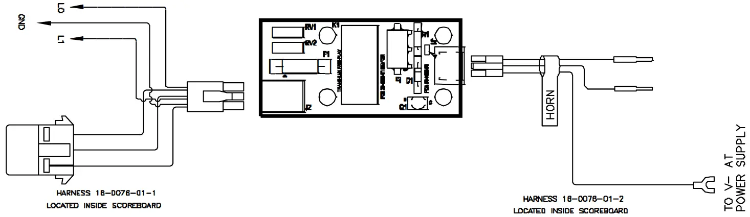
1. HARNESS TO HORN
2. HARNESS TO DRIVER
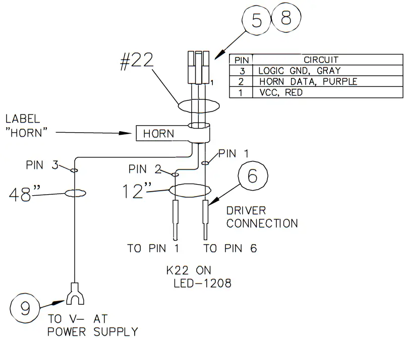
| B | CHANGED WIRE LENGTH ON BOTH, REMOVED RING DN #1 | 10/06/03 | DLS |
| A | #1. – CHANGED PINNING ORDER | 4/25/03 | DLS |
| 1 | ORIGINAL RELEASE | 1/23/03 | DLS |
| REV.# | CHANCE | DATE | BY |
HAZELWOOD, MO 63042 fair-play.corn | THIS DOCUMENT CONTAINS FAIR-PLAY PROPRIETARY INFORMATION. ANY DISCLOSURE, USE, OR DUPLICATION OF THE DOCUMENT OR OF ANY INFORMATION CONTAINED THEREIN FOR OTHER THAN THE SPECIFIC PURPOSE FOR WHICH IT WAS DISCLOSED IS EXPRESSLY PROHIBITED, EXCEPT AS MAY BE OTHERWISE AGREED TO IN WRITING | |||
| TITLE HORN CARD HARNESSES USED WITH OUTDOOR LED-1208 | DRAWN BY DLS | A | MODEL: 120 VAC HORN | |
| DATE 4/14/00 | DWG. No. 16-0076-01 | |||
| SCALE NONE | ||||


