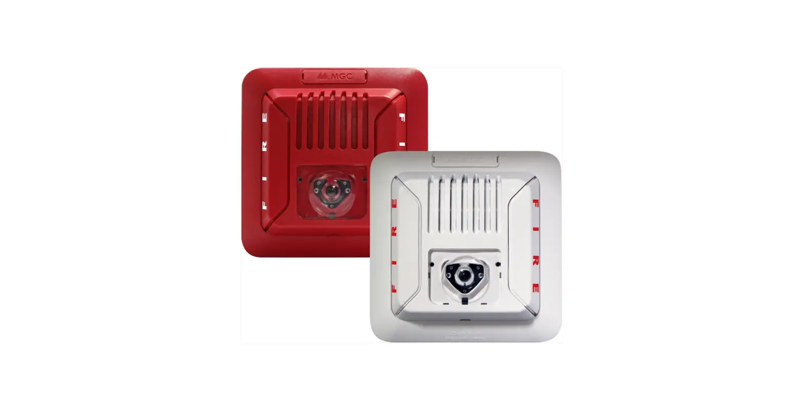
MGC LT-2078 Wall and Ceiling Mounted Horn
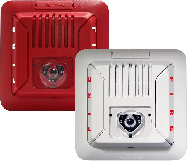
Wall and Ceiling Notifi cation Appliances
This manual applies to the following models
- Horn only
FH-400-WW and FH-400-RR – wall and ceiling mounted horn - Strobe only
- FS-400-WW and FS-400-RR – wall mounted strobe
- FS-400C-WW and FS-400C-RR – ceiling mounted strobe
- Horn and strobe
- FHS-400-WW and FHS-400-RR – wall mounted horn and strobe
- FHS-400C-WW and FHS-400C-RR – ceiling mounted horn and strobe
Note: WW indicates a white unit and RR indicates a red unit.
General Specifications
| Operating temperature: | 0°C to 50°C (32°F to 122°F) |
| Humidity range: | 0% to 93% |
| Strobe flash rate: | 1 Hz |
| Nominal Voltage: | Regulated 24 VDC / 24 VFWR |
| Operating Voltage Range (RMS): | 16 – 33 VDC / VFWR |
| Input terminal wire gauge: | 22 AWG to 12 AWG |
| Installation environment: | For indoor use only |
Caution
Do not change factory applied finishes
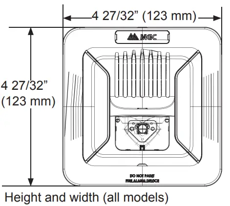
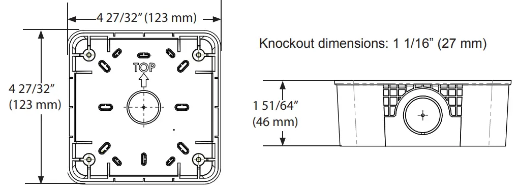
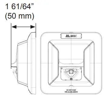
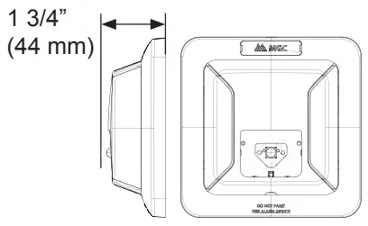
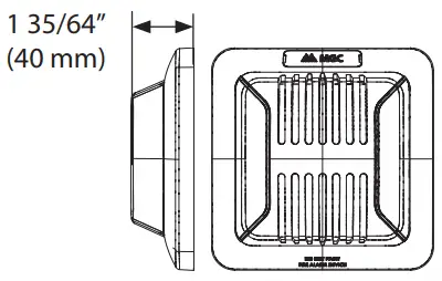
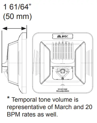
Dimensions for all Models
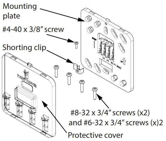
The kit includes
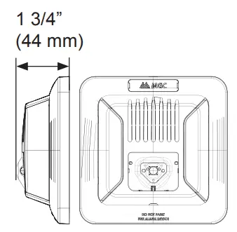
Dimensions of the Optional Mounting Box (BB-400R/W)
Setting the Candela (FS-400, FS-400C, FHS-400, FHS-400C only)
The candela can be set to 15, 30, 75, 15/75,110 and 185 (for FS-400 and FHS-400). The factory default setting is 15.
Note: The 185 candela setting is not available on ceiling units.
- Remove the plastic selector tab from the back of the device.
- Re-insert the selector tab into the notch that is labeled with the desired candela setting.

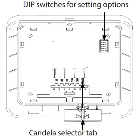
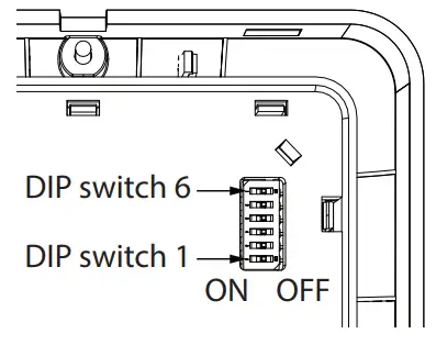
Setting the DIP Switches
Note: DIP switches 2 and 3 are not used.
Switch 1: Input
Note: Use Non-synchronized when the appliances do not need to be synchronized. Use Synchronized when synchronization is required, either through a sync module or built-in synchronization on the control unit.
| DIP Switch 1 | |
| ON | OFF |
| Regulated 24 VDC/FWR (Non- synchronized) | Synchronized (default) |
Switches 4 and 5: Signal Rate
| Signal Rate | DIP Switch 4 | DIP Switch 5 |
| Continuous | OFF | OFF |
| March | ON | OFF |
| Temporal (default) | ON | ON |
| 20 BPM | OFF | ON |
Switch 6: Horn volume
| DIP Switch 6 | |
| ON | OFF |
| High (default) | Low |
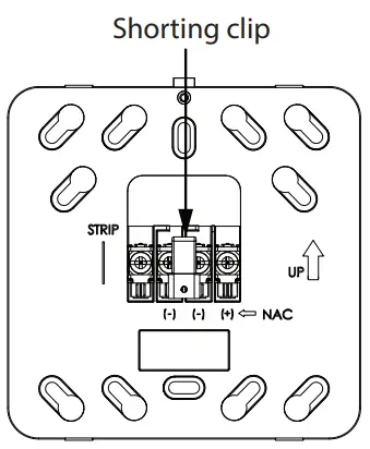
Shorting Clip
- In order to test the wiring, place the shorting clip on the middle two terminals after wiring.
- Remove the shorting clip before mounting the device.

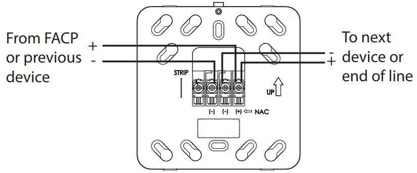
Wiring
- Use the information in this document to determine the total current draw of the devices. The total current draw of the devices must not exceed the power supply of the panel. In all cases, the installer should consider the voltage drop to ensure that the last device on the circuit operates within its rated voltage.
- The absolute maximum number of devices on one circuit is 100. The absolute maximum impedance for wall mounted devices at 15 candela is 150 ohms.
- Input terminal wire gauge: 22 AWG to 12 AWG
Note: Wiring must be in accordance with CSA C22.1, Canadian Electrical Code, Part I, Safety Standard for Electrical Installations, Section 32 and NFPA 70.
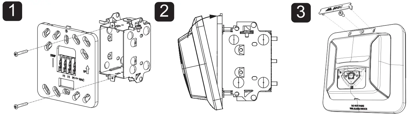
Mounting to the Wall or Ceiling
MGC recommends spacing notifi cation appliances in compliance with CAN/ULC S524 and NFPA 72. Mount the unit with the MGC logo at the top. The mounting plate is compatible with 3” by 2” single gang device boxes, 3-3/4” by 4” double gang boxes, 4” by 2” single gang utility boxes, standard 4” by 4” boxes, and standard 4” octagon boxes. See below for a description of the holes to use for each box.
- Attach the mounting plate to the box with 2 or 4 screws.
- Snap the unit on to the mounting plate.
- Secure the unit with the #4-40 x 3/8” screw and snap the nameplate over the screw.

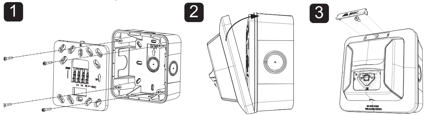
Mounting to the Optional Mounting Box (BB-400R/W)
MGC recommends spacing notifi cation appliances in compliance with CAN/ULC S524 and NFPA 72. Mount the unit with the MGC logo at the top.
- Attach the mounting plate to the mounting box with the 4 screws.
- Snap the unit on to the mounting plate.
- Secure the unit with the #4-40 x 3/8” screw and snap the nameplate over the screw.

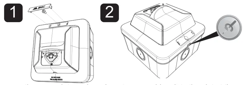
Unmounting
- Remove the nameplate and the screw.
- Insert a screwdriver into the slot at the top of the unit and turn it to separate the unit from the mounting plate.

Mounting Options
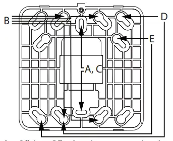
- A: 3” by 2” single gang device box
- B: 3 3/4” by 4” double gang box
- C: 4” by 2” single gang utility box
- D: standard 4” by 4” box
- E: standard 4” octagon box
Operating RMS Currents (mA)
FS-400 Strobe Operating RMS Currents (mA)
| Candela | Regulated 24 VDC | Regulated 24 VFWR |
| 15 | 25 | 64 |
| 30 | 39 | 106 |
| 75 | 102 | 189 |
| 15/75 | 93 | 189 |
| 110 | 105 | 189 |
| 185 | 179 | 241 |
FS-400C Strobe Operating RMS Currents (mA)
| Candela | Regulated 24 VDC | Regulated 24 VFWR |
| 15 | 37 | 93 |
| 30 | 72 | 152 |
| 75 | 152 | 217 |
| 15/75 | 153 | 216 |
| 110 | 226 | 256 |
Note: The 185 candela setting is not available on ceiling units.
FH-400 Horn Operating RMS Currents (mA)
| Volume | Regulated 24 VDC, all tones | Regulated 24 VFWR, all tones |
| High | 37 | 31 |
| Low | 22 | 25 |
FHS-400 Horn/Strobe Operating RMS Currents (mA)
| Regulated 24 VDC | Regulated 24 VFWR | |||
| Candela | Temporal Tone, High Volume * | Continuous Tone, High Volume | Temporal Tone, High Volume * | Continuous Tone, High Volume |
| 15 | 30 | 47 | 69 | 73 |
| 30 | 44 | 53 | 99 | 102 |
| 75 | 103 | 106 | 189 | 194 |
| 15/75 | 107 | 97 | 190 | 196 |
| 110 | 107 | 111 | 190 | 199 |
| 185 | 180 | 183 | 236 | 243 |
FHS-400C Horn/Strobe Operating RMS Currents (mA)
| Regulated 24 VDC | Regulated 24 VFWR | |||
| Candela | Temporal Tone, High Volume * | Continuous Tone, High Volume | Temporal Tone, High Volume * | Continuous Tone, High Volume |
| 15 | 41 | 52 | 95 | 98 |
| 30 | 75 | 80 | 160 | 164 |
| 75 | 155 | 158 | 228 | 232 |
| 15/75 | 156 | 158 | 227 | 233 |
| 110 | 227 | 231 | 258 | 261 |
Audible Ratings
dBA Reverberant Ratings per UL464 (dBA@10 ft) for FH-400, FHS-400, FHS-400C
| Sound Pattern | Volume | 16 VDC | Regulated 24 VDC | 33 VDC | 16 VFWR | Regulated 24 VFWR | 33 VFWR |
| Temporal | High | 82.2 | 84.9 | 84.6 | 76.8 | 79 | 80 |
| Low | 75.5 | 80.5 | 80.2 | 71.8 | 75.1 | 76.6 | |
| Continuous | High | 86.4 | 89.2 | 88.7 | 81.5 | 83.1 | 84 |
| Low | 79.9 | 84 | 84.8 | 76.2 | 79.3 | 81.2 | |
| 20 BPM | High | 79 | 81.3 | 81.6 | 74 | 75.1 | 76.1 |
| Low | 72.3 | 76 | 76.7 | 68.9 | 71.7 | 73.3 | |
| March | High | 83.2 | 86.4 | 85.7 | 79.2 | 80.6 | 81.4 |
| Low | 76.9 | 80.9 | 81.7 | 73.3 | 76.2 | 78 |
dBA Anechoic Ratings per CAN/ULC-S525 (dBA@3 m) for FH-400, FHS-400, FHS-400C
| Sound Pattern | Volume | 16 VDC | Regulated 24 VDC | 33 VDC | 16 VFWR | Regulated 24 VFWR | 33 VFWR |
| Temporal | High | 90.2 | 93.2 | 93.2 | 84.4 | 87.1 | 88.5 |
| Low | 83.7 | 87.4 | 88.3 | 78 | 82.2 | 84.5 | |
| Continuous | High | 90.2 | 93.2 | 93.3 | 85.1 | 87.8 | 89 |
| Low | 83.8 | 87.6 | 88.6 | 78.5 | 83 | 85 | |
| 20 BPM | High | 90.3 | 92.9 | 92.9 | 84.4 | 87.2 | 88.6 |
| Low | 83.6 | 87.3 | 88.3 | 78 | 82.2 | 84.5 | |
| March | High | 90.2 | 92.9 | 92.9 | 84.4 | 87.1 | 88.4 |
| Low | 83.7 | 87.4 | 88.3 | 78 | 82.2 | 84.4 |
ULC Directional Sound Characteristics for FH-400, FHS-400, FHS-400C
| Horizontal Axis | |
| ± 45° | -3 dbA |
| ± 61° | -6 dbA |
| ± 90° | -10 dbA |
| Vertical Axis | |
| ± 49° | -3 dbA |
| ± 61° | -6 dbA |
| ± 90° | -7.7 dbA |
Light Output Dispersion
Note: The following values are shown as percentages of the rated light output at any candela setting.
|
Degrees | % of Candela Rating | |||
| Horizontal Dispersion for FHS- 400 and FS-400 | Vertical Dispersion, Wall to Floor for FHS-400 and FS-400 | Vertical Dispersion X-Plane for FHS- 400C and FS-400C | Vertical Dispersion, Y-Plane for FHS- 400C and FS-400C | |
| ±0 | 149 | 148 | 150 | 155 |
| ±5 | 146 | 149 | 149 | 153 |
| ±10 | 143 | 153 | 149 | 152 |
| ±15 | 138 | 135 | 145 | 152 |
| ±20 | 134 | 104 | 139 | 146 |
| ±25 | 128 | 101 | 130 | 130 |
| ±30 | 123 | 94 | 121 | 122 |
| ±35 | 116 | 92 | 114 | 115 |
| ±40 | 106 | 84 | 111 | 111 |
| ±45 | 99 | 75 | 110 | 108 |
| ±50 | 92 | 68 | 110 | 108 |
| ±55 | 87 | 65 | 107 | 105 |
| ±60 | 82 | 61 | 100 | 101 |
| ±65 | 78 | 58 | 88 | 89 |
| ±70 | 75 | 54 | 72 | 72 |
| ±75 | 73 | 49 | 59 | 59 |
| ±80 | 72 | 43 | 60 | 61 |
| ±85 | 81 | 40 | 55 | 58 |
| ±90 | 53 | 30 | 42 | 45 |
| Compound ±45° | 42 | 79 | 83 | |
Limitations
These devices cannot operate on coded power supplies.
Disclaimer of Warranties and Limitation of Remedies and Liability
- MGC Systems Corp. (“MGC” or the “Company”) makes no warranty of merchantability or fi tness for a particular purpose with respect to its goods, nor is there any other warranty, expressed or implied, except for the warranty contained herein and in MGC’s standard terms of sale. All previous warranties are expressly revoked and no derivation or alteration, verbal or written, is authorized.
- MGC’s sole and exclusive obligation is to repair or replace, at its option, any part which is deemed by MGC to be defective in materials or workmanship under normal use and service, for a period of 12 months from the date of purchase, but not to exceed 18 months after shipment. MGC’s warranty shall be voided if the product is altered or serviced by a non-authorized party. MGC does not represent that its products will prevent loss by fi re or otherwise, or that its products will in all cases provide the protection for which its products are installed or intended. Buyer and end-users acknowledge that MGC is not an insurer and assumes no risk for loss or damage, other than as expressly agreed to by MGC in its warranty.
- Under no circumstances shall MGC’s liability, under warranty or otherwise, exceed the contract price for the goods for which liability is claimed, and in no event shall the Company be liable to the purchaser or any other third party for (a) consequential, collateral, incidental or special damages, including, without limiting the generality of the foregoing, loss of profi ts, loss of the product or any associated equipment, cost of capital, cost of substitute or replacement equipment, facilities or services, down time, purchaser’s time, labor back charges, the claims of third parties, including customers, and injury to property or other incidental costs incurred by purchaser or any third party, or (b) direct damages (other than direct damages as expressly specifi ed above).
ABOUT COMPANY
- CANADA – Main Oce
- 25 Interchange Way
- Vaughan, ON L4K 5W3
- Tel:
- (888) 660-4655
- (905) 660-4655
- Fax: (905) 660-4113
- U.S.A
- 4575 Witmer Industrial Estates
- Niagara Falls, NY 14305
- Tel:
- (888) 660-4655
- (905) 660-4655
- Fax: (905) 660-4113


