![]()
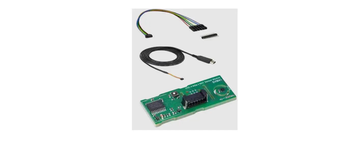
SENSIRION SVM41 Evaluation

General Considerations
For detailed information about the I2C protocol itself and its detailed implementation, please, consult the document NXP I2C-bus specification and user manual. All SVM41 commands consist of two bytes (16 bits). The commands must not be followed by a CRC. Additionally, data sent to and returned from the sensor is transferred in packets of two bytes (16 bits) followed by a 1-byte (8 bit) CRC.
I2C Address
The sensor’s I2C address is 106 (decimal; hex.: 0x6A). The I2C header is formed by the I2C address followed by a read or write bit.
I2C Voltage Levels
Input and output voltage levels are specified in section 6.1 of NXP I2C-bus specification and user manual. The sensor’s interface is compatible with 3.0–5.5 V I2C bus voltage levels depending on the supply voltage level.
I2C Protocol Speed
The sensor supports I2C “standard-mode” with a maximum clock frequency of 100 kHz.
I2C Sequences
The typical communication sequence between the I2C master (e.g., a microcontroller in a host device) and the SVM41 is described as follows and visualized in Figure 1:
- The SVM41 is powered up
- The I2C master starts the measurement of all sensors by calling the dedicated command.
- The I2C master periodically calls the get signals command and reads data in the following sequence:
- I2C master sends a get signals command.
- I2C master either waits for the expected duration (as listed in Table 2) or polls data until the read header is acknowledged by the slave.
- I2C master reads out the signal data.
- The I2C master may stop the measurement by sending the dedicated command.
With the acknowledgement of the start measurement command, both SGP41 and STH4x start measuring. Measurement data are continuously stored on the microcontroller with a sampling interval of 1 s. Resulting data can be retrieved at any time by sending one of the get signals commands. In case the sampling interval by the I2C master is higher than 1 s the slave will respond with the same data for 1 s. When the execution of the command is in progress, no communication with the sensor is possible and the sensor aborts the communication with a NACK condition. After sending one of the get signals commands, the master can read the measurement results by sending an I2C read header. The sensor will acknowledge the reception of the read header and responds with data. The response data length is listed in Table 2 and is structured in data words, where one word consists of two bytes of data (most significant bit first) followed by a one-byte CRC checksum. Each byte must be acknowledged by the master with an ACK condition for the sensor to continue sending data. If the sensor does not receive an ACK from the master after any byte of data, it will not continue sending data.
After receiving the checksum for the last word of data, a NACK and STOP condition have to be sent (see Figure 1). The I2C master can abort the read transfer with a NACK followed by a STOP condition after any data byte if it is not interested in subsequent data, e.g., the CRC byte or following data bytes, in order to save time. Note that the data cannot be read more than once, and access to data beyond the specified amount will return a pattern of high bits.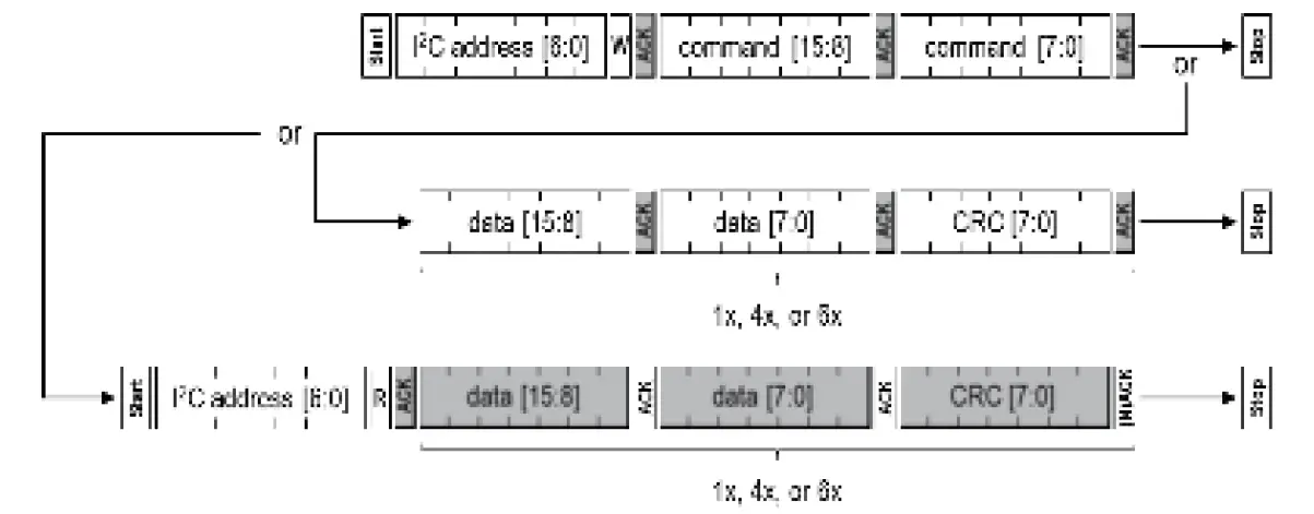 Possible I2C command sequences for communicating with the SVM41. Dark areas indicate that the SVM41 controls the SDA (data) line. First, the I2C master sends the write header writing a 16-bit command, potentially followed by one, four, or six words of data with CRC bytes. For reading the measured data, the I2C master sends the read header and receives one, four, or six words of data with CRC byte.
Checksum Calculation
The 8-bit CRC checksum transmitted after each data word is generated by the CRC algorithm according to the properties as stated in Table 1. The CRC covers the contents of the two previously transmitted data bytes.
| Property | Value | Example code |
| Name | CRC-8 | uint8_t CalcCrc(uint8_t data[2]) { uint8_t crc = 0xFF; for(int i = 0; i < 2; i++) { crc ^= data[i]; for(uint8_t bit = 8; bit > 0; –bit) { if(crc & 0x80) { crc = (crc << 1) ^ 0x31u; } else { crc = (crc << 1); } } } return crc; } |
| Width | 8 bit | |
| Protected Data | read and/or write data | |
| Polynomial | 0x31 (x8 + x5 + x4 + 1) | |
| Initialization | 0xFF | |
| Reflect input | False | |
| Reflect output | False | |
| Final XOR | 0x00 | |
| Examples | CRC (0xBE 0xEF) = 0x92 |
Checksums are used for the 2-byte data packets only. The command codes themselves already contain a 3-bit CRC and therefore, a checksum must not be appended.
I2C Commands
The available measurement commands of the SVM41 are listed in Table 2.
| Command | Command hex. code | Function | Send command during | Parameter length including CRC [bytes] | Response length including CRC [bytes] | Max. duration [ms] |
| svm41_start_measurement | 0x00 0x10 | – | idle mode | – | – | 1 |
| svm41_get_signals | 0x04 0x05 | – | measure mode | – | 12 | 1 |
| svm41_get_raw_signals | 0x03 0xD2 | – | measure mode | – | 12 | 1 |
| svm41_stop_measurement | 0x01 0x04 | – | measure mode | – | – | 50 |
| svm41_get/set_temperature_offset | 0x60 0x14 | get | idle or measure mode | – | 3 | 1 |
| set | idle mode | 3 | – | 1 | ||
| svm41_get/set_voc_parameters | 0x60 0xD0 | get | idle or measure mode | – | 18 | 1 |
| set | idle mode | 18 | – | 1 | ||
| svm41_get/set_voc_parameters | 0x60 0xE1 | get | idle or measure mode | – | 18 | 1 |
| set | idle mode | 18 | – | 1 | ||
| svm41_store_input_parameters | 0x60 0x02 | idle or measure mode | – | – | 500 | |
| svm41_get/set_voc_states | 0x61 0x81 | get | measure mode | – | 12 | 1 |
| set | idle mode | 12 | – | 1 | ||
| svm41_get_device_version | 0xD1 0x00 | – | idle or measure mode | – | 12 | 1 |
| svm41_reset_device | 0xD3 0x04 | – | idle or measure mode | – | – | 100 |
Start Measurement
Description of the I2C get signals command.
| Command | Command hex. code | Description |
| svm41_get_signals | 0x04 0x05 | This command reads out relative humidity, temperature as well as VOC and NOx Index. It returns 4×2 bytes (+ 1 CRC byte each). |
Returned values by the I2C get signals command.
| Byte number | Description | Value |
| 0, 1 | two bytes | int16 provides the relative humidity (in % RH) compensated for the temperature offset with a scaling factor of 100, e.g., an output of +2’500 corresponds to +25.00 % RH. |
| 2 | CRC byte for bytes 0, 1 | – |
| 3, 4 | two bytes | int16 provides the temperature (in °C) with a scaling factor of 200, e.g., an output of +5’000 corresponds to +25.00 °C. |
| 5 | CRC byte for bytes 3, 4 | – |
| 6, 7 | two bytes | int16 provides the VOC Index (no unit) with a scaling factor of 10, e.g., an output of +250 corresponds to a VOC Index of +25.0. |
| 8 | CRC byte for bytes 6, 7 | – |
| 9, 10 | two bytes | |
| 11 | CRC byte for bytes 9, 10 | int16 provides the NOx Index (no unit) with a scaling factor of 10, e.g., an output of +250 corresponds to a NOx Index of +25.0. |
Get Raw Signals
Description of the I2C get raw signals command.
| Command | Command hex. code | Description |
| svm41_get_raw_signals | 0x03 0xD2 | This command reads out relative humidity and temperature which are not compensated for temperature offset, and the VOC and NOx raw signals (proportional to the logarithm of the resistance of the MOX layer). It returns 4×2 bytes (+ 1 CRC byte each). |
Returned values by the I2C get raw signals command.
| Byte number | Description | Value |
| 0, 1 | two bytes | int16 provides the uncompensated relative humidity (in % RH) with a scaling factor of 100, e.g., an output of +2’500 corresponds to +25.00 % RH. |
| 2 | CRC byte for bytes 0, 1 | – |
| 3, 4 | two bytes | int16 provides the uncompensated temperature (in °C) with a scaling factor of 200, e.g., an output of +5’000 corresponds to +25.00 °C. |
| 5 | CRC byte for bytes 3, 4 | – |
| 6, 7 | two bytes | uint16 directly provides the VOC raw signal SRAW_VOC (in ticks) without scaling. |
| 8 | CRC byte for bytes 6, 7 | – |
| 9, 10 | two bytes | uint16 directly provides the NOx raw signal SRAW_NOX (in ticks) without scaling. |
| 11 | CRC byte for bytes 9, 10 | – |
Stop Measurement
Description of the I2C stop measurement command
| Command | Command hex. code | Description |
| svm41_stop_measurement | 0x01 0x04 | This command stops the operation mode of all sensors and returns the SVM41 to idle mode. |
Get/Set Temperature Offset for RHT Measurements
Description of the I2C get/set temperature offset command.
| Command | Command hex. code | Description |
| svm41_get_temperature_offset | 0x60 0x14 | This command, sent without parameter bytes, reads out the current temperature offset used for the compensation of RHT measurements by returning 2 bytes (+ 1 CRC byte). |
| svm41_set_temperature_offset | 0x60 0x14 0xXX 0xXX 0xXX Example with default value: 0x60 0x14 0x00 0x00 0x81 | This command sets the temperature offset used for the compensation of subsequent RHT measurements when sent together with input 2 bytes (+ 1 CRC byte) = 0xXX…0xXX. |
Returned/input values by the I2C get/set temperature offset command.
| Byte number | Description | Value |
| 0, 1 | two bytes | int16 provides the temperature offset (in °C) with a scaling factor of 200, e.g., an output of +400 corresponds to +2.00 °C. Default is 0 °C. |
| 2 | CRC byte for bytes 0, 1 | – |
Get/Set Parameters of VOC Algorithm
Description of the I2C get/set VOC parameters command.
| Command | Command hex. code | Description |
| svm41_get_voc_parameters | 0x60 0xD0 | This command, sent without parameter bytes, reads out the current six parameters used for the VOC Algorithm by returning 6×2 bytes (+ 1 CRC byte each). |
| svm41_set_voc_parameters | 0x60 0xD0 0xXX 0xXX 0xXX 0xXX 0xXX 0xXX 0xXX 0xXX 0xXX 0xXX 0xXX 0xXX 0xXX 0xXX 0xXX 0xXX 0xXX 0xXX | This command sets the four parameters used for the VOC Algorithm when sent together with 6×2 input bytes (+ 1 CRC byte each) = 0xXX…0xXX. |
| Example with default values: | ||
| 0x60 0xD0 0x00 0x64 0xFE 0x00 0x0C 0xFC 0x00 0xB4 0xFA 0x00 0x32 0x26 0x00 0xE6 0xE6 |
Returned/input values by the I2C get/set VOC parameters command.
| Byte number | Description | Value |
| 0, 1 | two bytes | int16 directly provides VOC Index (no unit) value representing the average conditions. Default is VOC Index = 100. Range is 1–250. |
| 2 | CRC byte for bytes 0, 1 | – |
| 3, 4 | two bytes | int16 directly provides learning time (in h) which is used by the VOC Algorithm to estimate its offset from the history. Events longer than approx. twice the learning time will be forgotten. Default is 12 h. Range is 1–1’000 h. |
| 5 | CRC byte for bytes 3, 4 | – |
| 6, 7 | two bytes | int16 directly provides learning time (in h) which is used by the VOC Algorithm to estimate its gain from the history. Events longer than approx. twice the learning time will be forgotten. Default is 12 h. Range is 1–1’000 h. |
| 8 | CRC byte for bytes 6, 7 | – |
| 9, 10 | two bytes | int16 directly provides maximum gating duration (in min). During this period, the estimator of the VOC Algorithm states is frozen when the VOC Index is very high. Default is 180 min. 0 disables this feature. Range is 0–3’000 min. |
| 11 | CRC byte for bytes 9, 10 | – |
| 12, 13 | two bytes | int16 directly provides initial standard deviation (no unit) used during start-up of the sensor. During start-up period, a lower value boosts VOC events while a higher value decreases VOC events. Default is 50. Range is 10–5’000. |
| 14 | CRC byte for bytes 12, 13 | – |
| 15, 16 | two bytes | int16 directly provides the gain factor to amplify or to attenuate the VOC Index output. Default is 230. Range is 1–1’000. |
| 17 | CRC byte for bytes 15, 16 | – |
Get/Set Parameters of NOx Algorithm
Description of the I2C get/set NOx parameters command.
| Command | Command hex. code | Description |
| svm41_get_nox_parameters | 0x60 0xE1 | This command, sent without parameter bytes, reads out the current six parameters used for the NOx Algorithm by returning 6×2 bytes (+ 1 CRC byte each). |
| svm41_set_nox_parameters | 0x60 0xE1 0xXX 0xXX 0xXX 0xXX 0xXX 0xXX 0xXX 0xXX 0xXX 0xXX 0xXX 0xXX 0xXX 0xXX 0xXX 0xXX 0xXX 0xXX | This command sets the six parameters used for the NOx Algorithm when sent together with 6×2 input bytes (+ 1 CRC byte each) = 0xXX…0xXX. |
| Example with default values: | ||
| 0x60 0xE1 0x00 0x64 0xFE 0x00 0x0C 0xFC 0x02 0xD0 0x5C 0x00 0x32 0x26 0x00 0xE6 0xE6 |
Returned/input values by the I2C get/set NOx parameters command.
| Byte number | Description | Value |
| 0, 1 | two bytes | int16 directly provides NOx Index (no unit) value representing the average conditions. Default is VOC Index = 1. Range is 1– 250. |
| 2 | CRC byte for bytes 0, 1 | – |
| 3, 4 | two bytes | int16 directly provides learning time (in h) which is used by the NOx Algorithm to estimate its offset from the history. Events longer than approx. twice the learning time will be forgotten. Default is 12 h. Range is 1–1’000 h. |
| 5 | CRC byte for bytes 3, 4 | – |
| 6, 7 | two bytes | int16 directly provides learning time (in h) which would be used by the NOx Algorithm to estimate its gain from the history; however, it has no impact on the NOx Index output. This parameter is still in place for consistency reasons with the svm41_get/set_voc_parameters commands. This parameter must always be set to 12 hours (0x00 0x0C). |
| 8 | CRC byte for bytes 6, 7 | Set to 0xFC. |
| 9, 10 | two bytes | int16 directly provides maximum gating duration (in min). During this period, the estimator of the NOx Algorithm states is frozen when the NOx Index is very high. Default is 720 min. 0 disables this feature. Range is 0–3’000 min. |
| 11 | CRC byte for bytes 9, 10 | – |
| 12, 13 | two bytes | int16 directly provides initial standard deviation (no unit) which would be used during start-up of the sensor; however, it has no impact on the NOx Index output. This parameter is still in place for consistency reasons with the svm41_get/set_voc_parameters commands. This parameter must always be set to 50 (0x00 0x32). |
| 14 | CRC byte for bytes 12, 13 | Set to 0x26. |
| 15, 16 | two bytes | int16 directly provides the gain factor to amplify or to attenuate the NOx Index output. Default is 230. Range is 1–1’000. |
| 17 | CRC byte for bytes 15, 16 | – |
Store Input Parameters to Non-Volatile Memory
Description of the I2C store input parameters command.
| Command | Command hex. code | Description |
| svm41_store_input_parameters | 0x60 0x02 | This command stores all parameters previously sent to the slave via the svm41_set_temperature_offset and/or the svm41_set_voc_parameters commands to the non-volatile memory of SVM41. These parameters will not be erased during reset and will be used by the corresponding algorithms after start-up. To reset the storage to factory settings the master has to set all parameters to the default values followed by a subsequent call of the svm41_store_input_parameters command. |
Get/Set States of VOC Algorithm
Description of the I2C get/set VOC states command.
| Command | Command hex. code | Description |
| svm41_get_voc_states | 0x61 0x81 | This command, sent without parameter bytes, reads out the states of VOC Algorithm by returning 4×2 bytes (+ 1 CRC byte each). These values can be used to set the states (using the svm41_set_voc_states command) after resuming sensor operation, e.g., after a short interruption by skipping the initial learning phase of the VOC Algorithm. |
| svm41_set_voc_states | 0x61 0x81 0xXX 0xXX 0xXX 0xXX0xXX 0xXX 0xXX 0xXX 0xXX 0xXX0xXX 0xXX Example: 0x61 81 0x00 0x00 0x81 0x00 0x00 0x81 0x00 0x32 0x26 0x00 0x00 0x81 | This command sets the states of the VOC Algorithm when sent together with 4×2 input bytes (+ 1 CRC byte each) = 0xXX…0xXX, which were retrieved by the svm41_get_voc_states command before. This can be used when resuming sensor operation, e.g., after a short interruption by skipping the initial learning phase of the VOC Algorithm. |
Returned/input values by the I2C get/set VOC states command.
| Byte number | Description | Value |
| 0, 1 | two bytes | uint8[2] array of two bytes providing the states of the VOC Algorithm. |
| 2 | CRC byte for bytes 0, 1 | – |
| 3, 4 | two bytes | uint8[2] array of two bytes providing the states of the VOC Algorithm. |
| 5 | CRC byte for bytes 3, 4 | – |
| 6, 7 | two bytes | uint8[2] array of two bytes providing the states of the VOC Algorithm. |
| 8 | CRC byte for bytes 6, 7 | – |
| 9, 10 | two bytes | uint8[2] array of two bytes providing the states of the VOC Algorithm. |
| 11 | CRC byte for bytes 9, 10 | – |
Get Version of Device
Description of the I2C get device version command
| Command | Command hex. code | Description |
| svm41_get_device_version | 0xD1 0x00 | This command returns information on the hardware, firmware, and protocol by returning 4×2 bytes (+ 1 CRC byte each). |
Returned values by the I2C get device version command.
| Byte number | Description | Value |
| 0 | one byte | uint8 provides the major version number of the firmware. |
| 1 | one byte | uint8 provides the minor version number of the firmware. |
| 2 | CRC byte for bytes 0, 1 | – |
| 3 | one byte | bool provides the debug state of the firmware. |
| 4 | one byte | uint8 provides the major version number of the hardware. |
| 5 | CRC byte for bytes 3, 4 | – |
| 6 | one byte | uint8 provides the minor version number of the hardware. |
| 7 | one byte | uint8 provides the major version number of the protocol. |
| 8 | CRC byte for bytes 6, 7 | – |
| 9 | one byte | uint8 provides the minor version number of the protocol. |
| 10 | one byte | uint8 to be ignored. |
| 11 | CRC byte for bytes 9, 10 | – |
Device Reset
Description of the I2C reset device command.
| Command | Command hex. code | Description |
| svm41_reset_device | 0xD3 0x04 | This command performs a reset of the device and restarts the SVM41 in idle mode. Prior to executing the reset, the device will acknowledge the call. All previously set parameters sent by svm41_set_temperature_offset, svm41_set_voc_parameters, svm41_set_nox_parameters, and svm41_set_voc_states commands will be lost. The temperature offset and the parameters of both VOC and NOx Algorithm can be stored to the non-volatile memory of SVM41 by calling the svm41_store_input_parameters command. |
Revision History
| Date | Version | Page(s) | Changes |
| October, 2021 | 1.0 | All | Initial release |
| December, 2021 | 1.1 | All 10 | Editorial amendments Descriptions of bytes 6–8 and 12–14 in Table 14 revised |
Headquarters and Subsidiaries
Sensirion AG Laubisruetistr. 50 CH-8712 Staefa ZH Switzerland
phone: +41 44 306 40 00
fax: +41 44 306 40 30
[email protected] www.sensirion.com
Sensirion Taiwan Co. Ltd
phone: +886 3 5506701
[email protected]
Sensirion Inc., USA
phone: +1 312 690 5858
[email protected]
www.sensirion.com
Sensirion Japan Co. Ltd.
phone: +81 3 3444 4940
[email protected]
www.sensirion.com/jp
Sensirion Korea Co. Ltd.
phone: +82 31 337 7700~3
[email protected]
www.sensirion.com/kr
Sensirion China Co. Ltd.
phone: +86 755 8252 1501
[email protected]
www.sensirion.com/cn
www.sensirion.com


