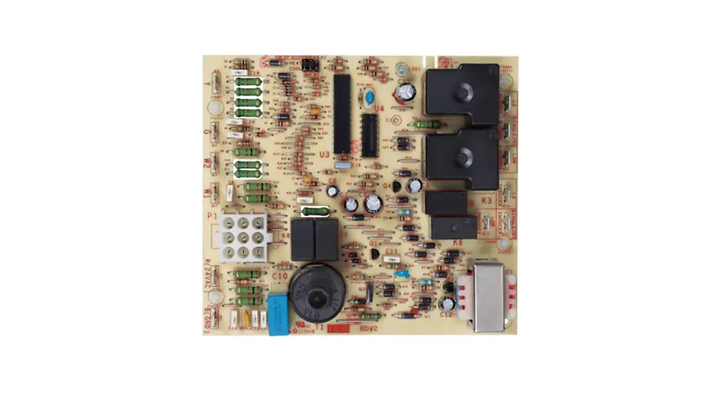
![]() 50N02B-820
50N02B-820
Integrated Furnace Control
INSTALLATION INSTRUCTIONS
FAILURE TO READ AND FOLLOW ALL INSTRUCTIONS CAREFULLY BEFORE INSTALLING OR OPERATING THIS CONTROL COULD CAUSE PERSONAL INJURY AND/OR PROPERTY DAMAGE.
DESCRIPTION
The 50N02B-820 is an Integrated Furnace Control for aftermarket service direct replacements on Trane Commercial Systems packaged units. Features 45 or 0-second cool fan off delay. First time replacement of the following controls will also require
Parts included:
• 50N02B-820 spark control
• Installation Instructions
• Diagnostic Indicator Tag
| Manufacturer | Part Numbers Requiring Adapter |
| Trane | CNT02219 |
SPECIFICATIONS
ELECTRICAL RATINGS:
Input Voltage: 18 to 33 VAC, 50-60 Hz
Current: 350 mA @ 24 VAC
Relay Contract Ratings:
Gas Valve Relay: 1.5 A 0.6 PF @ 24 VAC
Ignitor Relay: 5.0 A @ 132 VAC
Flame Current Requirements:
Min current to insure flame detection: 4.5 µA DC*
Max current for non-detection: 1.2 µA DC
Max allowable leakage resistance: 100 M ohms
*Measured with a DC microammeter in series with the flame probe lead
OPERATING TEMPERATURE RANGE:
-40° to 175°F (-40 to 80°C)
HUMIDITY RANGE:
To 95% relative humidity (non-condensing)
AGENCY APPROVALS: UL
GASES APPROVED: Natural, Manufactured, Mixed, Liquid
Petroleum, and LP Gas Air Mixtures
CAUTION
![]() Risk of Electric Shock.
Risk of Electric Shock.
Disconnect electric power to the system until installation is complete. Do not use on circuits exceeding specified voltage. Higher voltage will damage control and could cause shock or fire hazards.![]() This control is not intended for use in locations where it may come in contact with water.
This control is not intended for use in locations where it may come in contact with water.![]() May cause flame rollout. Shut off main gas to the heating system until installation is complete.
May cause flame rollout. Shut off main gas to the heating system until installation is complete.
INSTALLATION
MOUNTING AND WIRING
NOTE: All wiring should be installed according to local and national electrical codes and ordinances.
- Disconnect electrical power and gas supply to the unit, then remove the unit access panel.
- Mark and disconnect all wires from the existing control, then remove the old control.
- Rotate the new control such that the spark transformer and 9 pin connector are in the lower right-hand corner of the control board. Align the plastic standoffs on the new control with the remaining holes on adapter board 00594821 (from F50N02-820 Kit) and press on the board until all 4 plastic standoffs on the 50N02B-820 control snap firmly into place.
- Replace all of the wires, ensuring that the labels match the same designation on the new board, except, a single-stage gas furnace (old control #CNT02216) should have the “Indoor Fan Low” wire connected to the “BLOWER SINGLE/HI” terminal on the new #CNT03457 control, and the “Inducer Low” wire connected to the “INDUCER
SINGLE/HI” terminal on the new control because it is for a SINGLE stage furnace. - a) If the old control #CNT02216 is coming out of a single-stage gas furnace, then use the 9 pins to 9 pin wiring adapter harness (from F50N02-820 Kit) b) If the old control #CNT02217 or CNT02219 is coming out of a dual-stage gas furnace, then use the 9 pins to 12 pin wiring adapter harness (from F50N02-820 Kit).
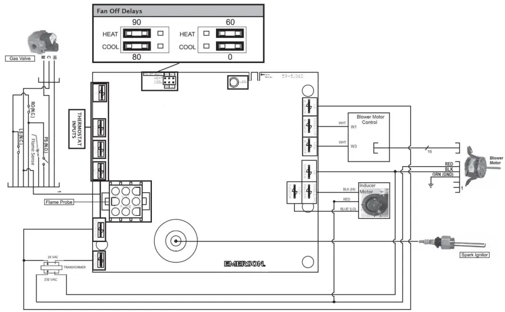
- Adjust Heat and Cool fan off delay jumpers as necessary.
NOTES:
- Even though the 50N02B-820 is set up to handle a dual-stage gas furnace, it will automatically configure itself to be a single-stage gas furnace control.
- “W” (old board) is equivalent to “W1” on 50N02B-820.
- “Indoor Fan” (old board) is equivalent to “Blower” on 50N02B-820.
WIRING DIAGRAM 
| Old Control# | Quick-Connect Terminal | New Control# | Quick-Connect Terminal | Comments |
| CNT02216 | CNT03457 50NO2A-820 | Single-Stage Gas Furnace The new module automatically configures to single-stage gas furnace operation | ||
| Y | Y | |||
| G | G | |||
| W2 | No wire to connect to the terminal | |||
| W | W1 | |||
| R | R (24 VAC) | |||
| B | B (GND) | |||
| Indoor Fan L2 | Blower L2 | |||
| Indoor Fan LOW | Blower SINGLE/HI | Due to “single” stage furnace | ||
| Blower LOW | Now wire to connect to the terminal | |||
| Inducer L2 | Inducer L2 | |||
| Inducer LOW | INDUCER SINGLE/HI | Due to “single” stage furnace | ||
| Inducer LOW | No wire to connect to the terminal | |||
| 9 pin connector | 9 pin connector | *9 pins to 9 pin wiring adapter harness* |
| Old Control# | Quick-Connect Terminal | New Control# | Quick-Connect Terminal | Comments |
| CNT02217 | CNT03457 50NO2A-820 | Dual-Stage Gas Furnace | ||
| Y | Y | |||
| G | G | |||
| W2 | W2 | |||
| W | W1 | |||
| R | R (24 VAC) | |||
| B | B (GND) | |||
| Indoor Fan L2 | Blower L2 | |||
| Indoor Fan LOW | Blower LOW | |||
| Indoor Fan HIGH | Blower SINGLE/HI | |||
| Inducer L2 | Inducer L2 | |||
| Inducer LOW | Inducer LOW | |||
| Inducer HIGH | Inducer SINGLE/HI | |||
| 12 pin connector | 9 pin connector | *12 pins to 9 pin wiring adapter harness* | ||
| CNT02219 | CNT03458 50NO2B-820 | Dual-Stage Gas Furnace with ICM Motor | ||
| Y | Y | |||
| G | G | |||
| W2 | W2 | |||
| W | W1 | |||
| R | R (24 VAC) | |||
| B | B (GND) | |||
| ICMC Module R | Blower L2 | |||
| ICMC Module HIGH | Blower SINGLE/HI | |||
| ICMC Module LOW | Blower LOW | |||
| Inducer L2 | Inducer L2 | |||
| Inducer LOW | Inducer LOW | |||
| Inducer HIGH | Inducer SINGLE/HI | |||
| 12 pin connector | 9 pin connector | *12 pins to 9 pin wiring adapter harness* |
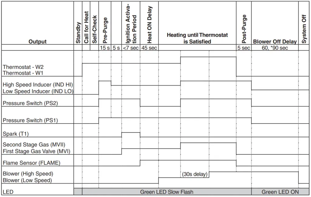
OPERATION
COOL MODE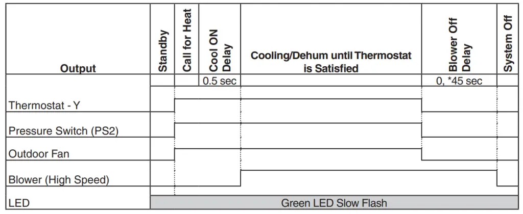 FAN MODE
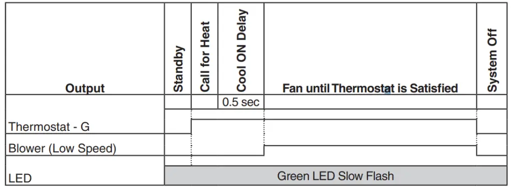
TROUBLESHOOTING
DIAGNOSTIC CODES
The green LED will indicate a status code as shown in the table below:
| Green LED Flash Code | Status / Error Condition |
| Steady OFF | No Power / Failure / Internal Failure |
| Steady ON | Normal, no call for heat |
| Slow Flash Rate | Normal, call for heat |
| 2 Flashes | System Lockout: Failed to detect or sustain flame |
| 3 Flashes | Pressure switch problem detected |
| 4 Flashes | High Limit switch protection device open |
| 5 Flashes | Flame sensed and gas valve not energized or flame sensed and no “W” signal |
| 6 Flashes | Flame Rollout Switch open |
| 7 Flashes | Thermostat miswired; W1 and W2 swapped |
TECHNICAL SUPPORT: 1-888-725-9797![]()
white-rodgers.com
emerson.com
Emerson and White-Rodgers are trademarks of Emerson Electric Co. ©2017 Emerson Electric Co. All rights reserved.![]() white-rodgers.com
white-rodgers.com
emerson.com


