 THE FUTURE IS WHAT WE MAKE IT
Gateway
GW-1000-WE/GW-1000-NWE
INSTALLATION INSTRUCTIONS
GENERAL SAFETY INFORMATION
- When performing any work (installation, mounting, start-up), all manufacturer instructions and in particular the Installation and Commissioning Instructions (EN1B- 0205IE10) are to be observed.
- The gateway may be installed and mounted only by authorized and trained personnel.
- Rules regarding electrostatic discharge should be followed.
- If the GW-1000-WE/GW-1000-NWE gateway is modified in any way, except by the manufacturer, all warranties concerning operation and safety are invalidated.
- Make sure that the local standards and regulations are observed at all times. Examples of such regulations are VDE 0800 and VDE 0100 or EN 60204-1 for earth grounding.
- Use only accessory equipment which comes from or has been approved by Honeywell.
- It is recommended that devices be kept at room temperature for at least 24 hours before applying power. This is to allow any condensation resulting from low shipping/storage temperatures to evaporate.
- The GW-1000-WE/GW-1000-NWE gateway must be installed in a manner (e.g., in a lockable cabinet) ensuring that uncertified persons have no access to the terminals.
- Investigated according to United States Standard UL60730-1, UL-916, and UL60730-2-9.
- Investigated according to Canadian National Standard(s) C22.2, No. 205-M1983 (CNL-listed).
- Do not open the GW-1000-WE/GW-1000-NWE gateway, as it contains no user-serviceable parts inside.
- CE declarations according to LVD Directive 2014/35/EU and EMC Directive 2014/30/EU.
- Product standards are EN 60730-1 and EN 60730-2-9.
Professional Installation
- This device must be professionally installed, this should be noted on the grantee.
- To maintain compliance, only the antenna types that have been tested shall be used, which are listed in the “Remote Antenna Part Numbers” section on page 14. This device requires significant technology engineering expertise towards an understanding of the tools and relevant technology, not readily available to the average consumer. Only a person professionally trained in the technology is competent.
- This device is not directly marketed or sold to the general public.
Safety Information as per EN60730-1
The GW-1000-WE/GW-1000-NWE gateway is intended for residential, commercial, and light-industrial environments. The GW-1000-WE/GW-1000-NWE gateway is an
independently mounted electronic control system with fixed wiring.
The GW-1000-WE/GW-1000-NWE gateway is suitable for mounting in fuse boxes conforming with standard DIN43880, and having a slot height of max. 45 mm.
It is suitable for panel rail mounting on 35 mm standard panel rail (both horizontal and vertical rail mounting possible).
The GW-1000-WE/GW-1000-NWE gateway is used for the purpose of building HVAC control and is suitable for use only in non-safety controls for installation on or in appliances.
Table 1. Safety Information as per EN60730-1
| Electric Shock Protection | PELV |
| Pollution Degree | Pollution Degree 2, suitable for use in industrial environments. |
| Installation | Class 3 |
| Overvoltage Category | 24 V-powered controls: Category I |
| Rated Impulse Voltage | 330 Vac for Category I (SELV) |
| Automatic Action | TypetY |
| Software Class | Class A |
| Enclosure | IP20 according to EN-60529 |
| Ball-pressure Test Temperature | >75 °C for all housing and plastic parts >125 °C in the case of devices applied with voltage-carrying parts, connectors, and terminals. |
| Electromagnetic Interference | Tested at 230 Vac, with the modules in normal condition. |
| System Transformer | Europe: safety isolating transformers according to IEC61558-2-6 U.S.A. and Canada: NEC Class-2 transformers |
WEEE

WEEE Directive 2012/19/EC Waste Electrical and Electronic Equipment Directive
- At the end of the product life, dispose of the packaging and product in an appropriate recycling center.
- Do not dispose of the device with the usual domestic refuse.
- Do not burn the device.
TECHNICAL DATA
Electrical Data
Table 2. Electrical Data
| Operating Voltage (AC) | 19 to 29 Vac (50/60Hz) |
| Operating Voltage(DC) | 19 to 29 Vdc |
| Screw-type Terminals | 2.5 mm2 |
| Overvoltage Protection | Protected against overvoltages of max. 29 Vac or 40 Vdc, terminals are protected against short-circuiting. |
Power Consumption
Table 3. Power Consumption
| Gateway | Power | |
| 24Vac | 24Vdc | |
| GW-1000-WE/GW1000-NWE | Max. 35VA | Max. 15W |
Current Consumption
Table 4. Current Consumption
| Gateway | Power | |
| 24Vac | 24Vdc | |
| GW-1000-WE/GW1000-NWE | 1430mA | 620mA |
Operational Environment
Table 5. Operational Environment
| Ambient Operating Temperature | 0 to 50 °C (32 to 122 °F) |
| Ambient Operating Humidity | 5 to 950/0 relative humidity (non-condensing) |
| Ambient Storage Temperature | -28.9 to +70°C (-20 to 158 °F) |
| Ambient Storage Humidity | 5 to 950/0 relative humidity (non-condensing) |
| Vibration Under Operation | 0.024″ double amplitude (2 to 30 Hz). 0.6 g (30 to 300 Hz) |
| Dust. Vibration | According to EN60730-1 |
Table 5. Operational Environment
| RFI, EMI | Residential, commercial, and light-industrial environments |
| MTBF (Mean Time Between Failure) | 11.5 years |
Default IP Address
Table 6. Default IP Address
| IP Address | 192.168.2.1 (applicable only when Gateway is in AP mode) |
| Net Mask | 255.255.255.0 |
Standards
Table 7. Standards
| Protection Class | IP20 |
| Product Standards | CAN/CSA-E60730-1:02, Ethernet Protocol version IEEE 802.3 |
| Testing Electrical Components | IEC68 |
| Certification | •UL60730-1 •UL916 •EN 60730-1 •EN 60730-2-9 •FCC Part15, Subpart B •CAN ICES-3 (B)/NMB-3(B) •BQB •RoHS II •REACH |
| System Transformer | The system transformer(s) must be safety isolating transformers according to IEC 61558-2-6. In the U.S.A. and Canada, NEC Class 2 transformers must be used. |
INTERFACES
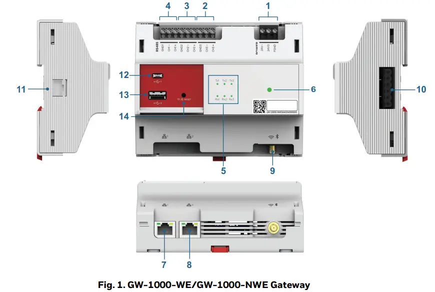 NOTE: *All RS485 interfaces, USB interfaces, RJ11 interface, Rx, and Tx LEDs are for future use.
Table 8. Gateway Terminals
| Type | Legend | Signal | Comment |
| Power Supply Terminals | 1 | FIND | Connect to earth ground in the field |
| 24V0 | Power supply common | ||
| 24V- | Power supply (24 Vac/dc) | ||
| *RS485 Interface 3 Terminals | 2 | CI-13+ | (+) for RS485 interface 3 |
| CH3- | (-) for RS485 interface 3 | ||
| GND3 | GND3 for RS485 interface 3 | ||
| *RS485 Interface 2 Terminals | 3 | CH2+ | (+) for R5485 interface 2 |
| CH2- | (-) for RS485 interface 2 | ||
| GND2 | GND2 for RS485 interface 2 | ||
| *RS485 Interface 1 Terminals | 4 | CH1+ | (+) for RS485 interface 1 |
| CH1- | (-) for RS485 interface 1 | ||
| GND1 | GND1 RS485 interface 1 | ||
| LED | 5 | *Txl LED (green) | Transmit and receive an indication for RS485 interfaces 1 to 3 |
| *Rxl LED (green) | |||
| *Tx2 LED (green) | |||
| *Rx2 LED (green) |
| Type | Legend | Signal | Comment |
| LED | 5 | *Tx3 LED (green) | Transmit and receive an indication for RS485 interfaces 1 to 3 |
| *Rx3 LED (green) | |||
| 6 | Main LED | Indicates the operational status of the Gateway | |
| RJ45 Interface | 7 | Ethernet 1 | Dedicated to Internet/Cloud connectivity (10/100/1000BASE-T) |
| 8 | Ethernet 2 | Dedicated to MultiTech LoRaWAN hub (10/100/1000BASE-T) | |
| SMA Terminal | 9 | For Wi-Fi and Bluetooth antenna | Antenna for both Wi-Fi and Bluetooth 802.11a/b/g/n/ac + BT 4.2 |
| *RS485 Interface 4 Terminals | 10 | – (24V-) | Communication and power bus for expansion modules |
| 24V0 | |||
| FIND | |||
| GND | |||
| (-) for RS485 interface 4 | |||
| (+) for RS485 interface 4 | |||
| *RJ11 Interface | 11 | (+) for RS485 interface 5 | |
| (-) for RS485 interface 5 | |||
| output 5Vdc | |||
| GND | |||
| *USB Interface | 12 | Micro USB port to connect with laptops, mobile, and tablets | |
| 13 | USB Type-A port | ||
| Reset Button | 14 | Reset button to reset the device to factory default |
Main LED
Table 9. Main LED Pattern
| LED behavior | Visual | Meaning |
| Green-Yellow-Red cycling (Alternate Green, Yellow, Red every 1.0 sec ) | Factory default • No Configuration in Gateway and Not Registered | |
| Solid Green | Working properly • Firmware Running and Connected to Cloud | |
| Yellow – breathing | Internet connection Status • Internet is connected | |
| Red – breathing | Wi-Fi connection: • AP Mode – Failed |
Table 9. Main LED Pattern
| LED behavior | Visual | Meaning |
| Blink every 0.2S Green | Firmware download or device configuration is in progress | |
| Blink every 0.2S Red | Total communication failure | |
| Three Blinks in the 1.5-second interval and then Pause for 2 sec Red | Internet/Cloud connection failure | |
| 2 Red Blinks and Pause | OS booting | |
| Yellow Slow Blink every 1 sec | Wi-Fi connection is in progress after device boot-up. |
Ethernet LEDs
Ethernet 1 is used for Cloud connectivity and Ethernet 2 is to connect with MultiTech HUB.
These are RJ45 female interfaces, each with a yellow activity status LED (located to the left) and a green activity LED (located to the right). The possible behaviors and corresponding meanings of these LEDs are explained in the following table.
Table 10. LEDs of Ethernet interfaces 1 and 2
| Case | LED Behavior | Meaning | Remedy |
| 1 | Yellow LED is ON steadily | Ethernet is working with connectivity up to 100Mbps. | If communication problems persist, then check the green LED. See Case 3 and Case 4 given below. |
| 2 | Yellow LED is OFF | •If the green LED is ON or flashing, then Ethernet is working with connectivity up to 10Mbps. •If the green LED is OFF, then Ethernet is disconnected | Connect the cable between the Gateway and the switch. |
| 3 | Green LED is flashing | Normal operation. The Gateway is transmitting/receiving data to/from the switch via cable. | If communication problems persist, the Ethernet parameter configuration may be defective: Check IP address, MAC address, and firmware. |
| 4 | Green LED is ON | Ethernet connectivity exists but no data flow. | Check the software configuration. |
| 5 | Green LED is OFF | The Ethernet port link is down. | •Check the cable connection between the Gateway and the switch. •Check the switch. •Use good a laptop or good cable to directly connect the Gateway and the switch |
The GW-1000-WE/GW-1000-NWE gateway has a reset button to reset the device to factory default. The user should push the button for 20 seconds to reset the Gateway. After reset, the Gateway will restart two times. The reset performs the following operations and completes in three minutes.
- Erases the Gateway configuration
- Resets the SSID to default
- Retains the user registration
- Retains the current firmware version
- Retains the current OS version
- LED Yellow breathing
Communication Baud Rates
Table 11. Communication Baud Rates
| Ethernet | 10/100/1000 Mbit/s, RJ45 |
| BACnet MSTP | 9.6, 19.2, 38.4, 76.8, 115.2 Kbps |
| Wi-Fi | 802.11b: up to 11Mbps 802.11g: up to 54Mbps 802.11n: up to 150Mbps |
| Bluetooth | BR: up to 1Mbps EDR: up to 3Mbps BLE: up to 1Mbps |
| Wi-Fi Range with unobstructed line of sight | 100 ft |
| Supported type of Wi-Fi connections | Wi-Fi Access Point – Providing access point to 10-10M IXR-WE/10- 10MIXR-NWE Smart 10 and TC500A-N Commercial Thermostat devices |
NOTE: Wi-Fi 5 GHz is for future use.
Connection to Honeywell Forge
GW-1000-WE/GW-1000-NWE Gateway uses HTTPS for connecting to the Honeywell Forge platform. It connects to the Internet via Ethernet 1 port.
Connection to MultiTech LoRaWAN Hub
GW-1000-WE/GW-1000-NWE Gateway uses UDP Port for its communication on Wifi and Ethernet 2. For more information, refer to the “Gateway to MultiTech LoRaWAN hub connection” section on page 10.
Small and Medium Building Administrator Supervisor Dashboard
For more information, refer to the Small and Medium Building Administrator Supervisor Dashboard user guide (31-00379M).
Honeywell Connect Mobile App
For more information, refer to the Small and Medium Building Administrator Deploy App Setup guide (3100451M).
POWER SUPPLY
 WARNING
Risk of electric shock or equipment damage!
- Do not connect more than one GW-1000-WE/GW1000-NWE gateway to the same transformer.
Transformers
Honeywell Transformers
A transformer can power the GW-1000-WE/GW-1000NWE gateway.
When determining total current consumption and selecting the appropriate transformer, take into account the number of connected modules, accessories, and field devices.
NOTE: In Europe, system transformer(s) must be safety isolating transformers according to IEC61558-26. In the U.S.A. and Canada, NEW Class-2 transformers must be used.
Table 12. Honeywell CRT Series Transformers (Europe)
| Part No. | Primary Side | Secondary Side |
| CRT 2 | 220/230 Vac | 24 Vac, 50 VA, 2 A |
| CRT 6 | 220/230 Vac | 24 Vac, 150 VA, 6 A |
| CRT 12 | 220/230 Vac | 24 Vac, 300 VA, 12 A |
Table 13. Honeywell 1450 Series Transformers (N. America)
| Part No. 14507287 | Primary Side | Secondary Side |
| -1 | 120 Vac | 24 Vac, 50 VA |
| -2 | 120 Vac | 2x 24 Vac, 40 VA; 100 VA from separate transformer |
| -3 | 120 Vac | 24 Vac, 100 VA; 24 Vdc; 600 mA |
| -4 | 240/220 Vac | 24 Vac, 50 VA |
| -5 | 240/220 Vac | 2 x 24 Vac, 40 VA; 100 VA from separate transformer |
| -6 | 240/220 Vac | 24 Vac, 100 VA; 24 Vdc, 600 mA |
NOTE: Standard commercially available transformers can also power the GW-1000-WE/GW-1000-NWE gateway.
Switch Mode Power Supply
To reduce overall current consumption, the GW-1000WE/GW-1000-NWE gateway can be powered by a switch-mode dc power supply (rather than by a transformer).
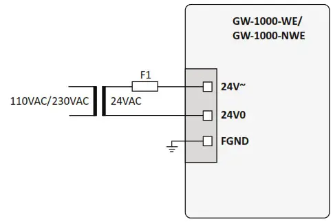
Fusing
The choice of appropriate fusing is dependent upon the given connection scenario (i.e., cable lengths and the use of a primary and/or secondary transformer) and upon the type of connected bus.
Table 14. Fusing
| Designation | Description |
| F1 | 4 A, time-lag fuse (slow-blow), e.g., Littelfuse type 218.004. |
| F2 | Depends upon field devices. |
WIRING AND SET-UP
General Safety Considerations
- When connecting the GW-1000-WE/GW-1000-NWE gateway, VDE, National Electric Code (NEC) or equivalent, and any local regulations concerning grounding must be observed.
- Only qualified electricians may carry out electrical work.
- The electrical connections must be made at the terminals of the GW-1000-WE/GW-1000-NWE gateway.
- For Europe, only: To comply with CE requirements, devices with a voltage in the range of 50 to 1000 Vac or 75 to 1500 Vdc and which are not provided with a supply cord and plug or with other means for disconnection from the supply having a contact separation of at least 3 mm in all poles must have the means for disconnection incorporated in the fixed wiring.
- Only copper conductors should be used for electrical connections.
- Only electrical cables/wires with operating temperatures at least 75° C should be used for electrical connection.
WARNING
Risk of electric shock or equipment damage!
- Do not touch any live parts in the cabinet.
- Disconnect the power supply before making connections to or removing connections from Gateway terminals.
- Do not use spare terminals as wiring support points.
- Do not reconnect the power supply until you have completed the power supply.
 CAUTION
Observe the precautions for handling electrostatic devices.
Wiring Terminals
The GW-1000-WE/GW-1000-NWE gateway features screw-type terminals.
Table 15. Power Supply Wiring Terminals Specifications
| Terminal Type | Stripping Length | TorqueValue | Max. Plug Gauge |
| Screw (Type P2) | 6mm | 3.1 to 3.5 lb-in (0.350 to 0.395 N-m) | 28 to 14 AWG (0.0804- 2.075 mm2 ) |
Terminals support both flexible and solid cables. Wires can be equipped additionally with ferrules.
Connecting Power Supply
Connect the power supply to the power supply terminals of the GW-1000-WE/GW-1000-NWE gateway. The factory default Gateway must be powered ON for a minimum of 10 hours for the first time to make the RTC function as intended.
Earth Grounding
The GW-1000-WE/GW-1000-NWE gateway comply with SELV (Safety Extra-Low Voltage), so protective earth grounding is not required. However, a functional earth grounding for EMC is mandatory. For information, see the “Appendix: Earth Grounding” section on page 13.
WIRING CONNECTIONS
Gateway to MultiTech LoRaWAN hub connection
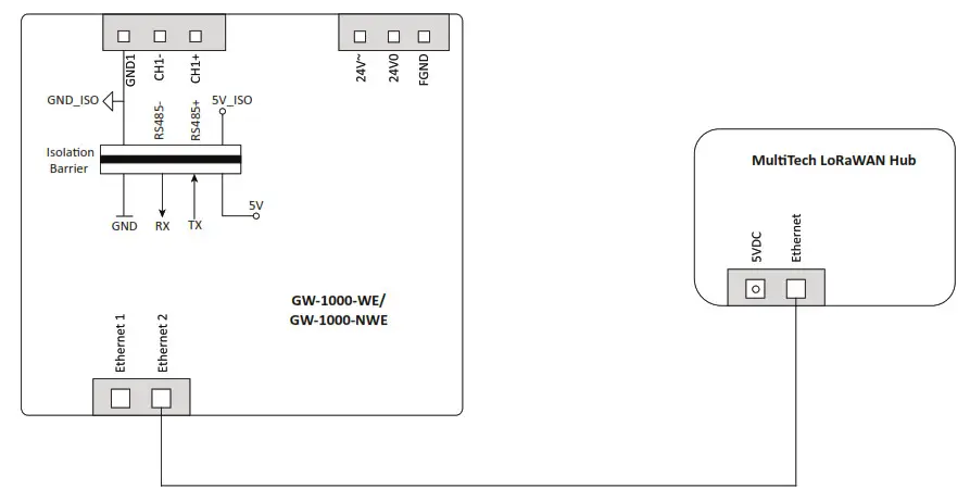
WARNING
Do not connect the MultiTech LoRaWAN Hub to Ethernet 1
If connected to Ethernet 1 mistakenly, then restart the MultiTech LoRaWAN Hub before connecting to Ethernet 2
WIRELESS CONNECTIVITY
Connectivity Frequency Range
Table 16. Connectivity Frequency Range
| Connectivity Medium | Frequency Range | E.I.R.Pfor CE | E.I.R.Pfor FCC/IC |
| Bluetooth | 2400 MHz- 2483.5 MHz | 20 mW | 20 mW |
| Wi-Fi 2.4 GHz | 2400 MHz- 2483.5 MHz | 100 mW | 320 mW |
NOTE: Wi-Fi 5 GHz is for future use.
General Information
- EMF Statement: To maintain compliance with the RF exposure requirement, a separation distance of 20 cm between the device and the human should be maintained.
- Alarm information in France
FCC Warning Statement: “This device complies with Part 15 of the FCC Rules. Operation is subject to the following two conditions:
1. This device may not cause harmful interference, and
2. This device must accept any interference received, including interference that may cause undesired operation.
- Changes or modifications not expressly approved by the party responsible for compliance could void the user’s authority to operate the equipment.
- This device complies with FCC radiation exposure limits set forth for an uncontrolled environment.
- This device must not be co-located or operating in conjunction with any other antenna or transmitter.
- End-users must follow the specific operating instructions for satisfying RF exposure compliance.
- FCC Class B Statement:NOTE: This equipment has been tested and found to comply with the limits for a Class B digital device, pursuant to part 15 of the FCC Rules. These limits are designed to provide reasonable protection against harmful interference in a residential installation. This equipment generates, uses, and can radiate radio frequency energy and, if not installed and used in accordance with the instructions, may cause harmful interference to radio communications. However, there is no guarantee that interference will not occur in a particular installation. If this equipment does cause harmful interference to radio or television reception, which can be determined by turning the equipment off and on, the user is encouraged to try to correct the interference by one or more of the following measures:
• Reorient or relocate the receiving antenna.
• Increase the separation between the equipment and receiver.
• Connect the equipment into an outlet on a circuit different from that to which the receiver is connected.
• Consult the dealer or an experienced radio/TV technician for help. - Changes or modifications not expressly approved by the party responsible for compliance could void the user’s authority to operate the equipment.
- IC Statement: This device complies with Industry Canada license-exempt RSS standard(s). Operation is subject to the following two conditions: (1) this device may not cause interference, and (2) this device must accept any interference, including interference that may cause undesired operation of the device.
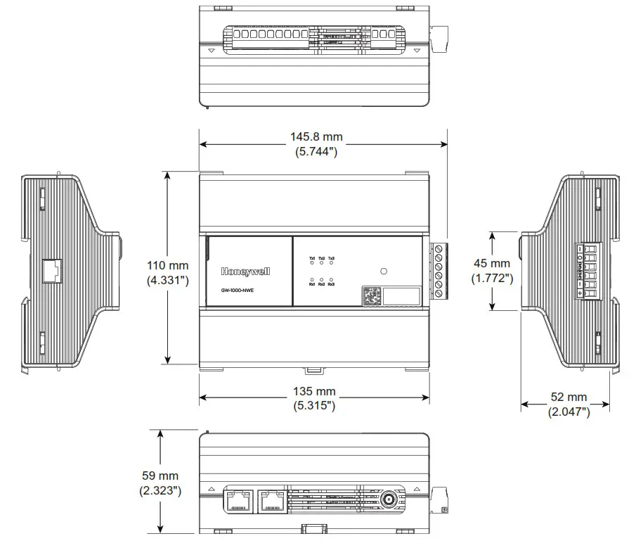
DIMENSIONS
GW-1000-WE/GW-1000-NWE Gateway
APPENDIX: EARTH GROUNDING
Gateway and SELV
In order to avoid the distribution of noise or earth-ground potential differences over networks or other connections, the GW-1000-WE/GW-1000-NWE gateway is designed to comply with SELV (Safety Extra Low Voltage).
Furthermore, SELV offers the greatest possible safety against electrical impact.
To support SELV, all Honeywell external (CRT series) or internal transformers comply with standard EN60742.
Earth grounding is therefore not recommended.
Gateway and EN60204-1
However, if compliance with the standard EN60204-1 is required, note the following:
General Information about EN60204-1
EN60204-1 defines electrical safety for a complete application/machine including Gateways, sensors, actuators, and any connected/controlled electrical device.
EN60204-1 requires Gateways to be powered by PELV (Protective Extra-Low Voltage) and earth grounding of the secondary side of the used transformers or earth grounding of the system ground. Earth grounding is prescribed to prevent the unexpected start-up of connected rotating/moving machines due to an insulation fault and double earth grounding somewhere in the plant.
The use of an earth leakage monitor is also possible to fulfill PELV if earth grounding is prohibited.
When is EN60204-1 Applicable to Gateway?
SAFETY AGAINST ELECTRICAL IMPACT
EN60204-1 is not mandatory; this is because electrical safety is provided by the use of SELV and transformers according to standard EN60742.
SAFETY AGAINST UNEXPECTED START-UP OF ROTATING/MOVING MACHINES
If the application/plant does not contain machines that can be harmful to the operator due to an unexpected startup, the standard EN60204-1is not applicable. If such machines are encountered, then EN60204-1 must be followed. Grounding is required.
Functional EMC Grounding
- Use a cable as short as possible for grounding: min 1.5 mm 2 (16 AWG).
- For connection details, refer to the following example.
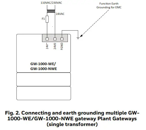
EXAMPLE
Connecting a single transformer with multiple GW-1000WE/GW-1000-NWE gateway earth-grounded as per EN60204-1.
- Connect earth ground to FGND of the GW-1000WE/GW-1000-NWE gateway.
NOTES:
— Use noise-free earth ground inside the cabinet.
— Use one star-point to split power for Gateways and field devices.
— If the transformer is used for several Gateways, each Gateway ground has to be wired separately to the start point.
— If a field device that prohibits earth grounding is connected to the system ground, an isolation monitoring device must be used instead of earth grounding.
— If the field device transformer is physically far away from the Gateway, earth grounding must still be performed for the Gateway.
GATEWAY PART NUMBERS
Table 17. Gateway Part Numbers
| Part Number | Description |
| GW-1000-WE | Wireless Gateway with European and Latin American conformance |
| GW-1000-NWE | Wireless Gateway with North American conformance |
Accessories Part Numbers
These accessories are available in separate orders.
Table 18. Accessories
| Part Number | Description | |
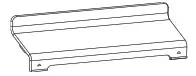 | GW-TCVR | Replacement Terminal Covers (Small) (Pack Quantity of 4) |
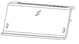 | GW-EXT-TCVR | Extended Terminal Covers (Large) (Pack Quantity of 4) |
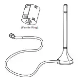 | ANT-REM | Remote Antennas with an adhesive magnetic foot for wireless communication. 1.5 meter (4.9 feet) cable length for remote mounting of the antenna. (Pack Quantity of 4) & Ferrite Ring Part Number: ZCAT3035-1330-BK Manufacturer: TDK |
| GW-ANT-LOC | Local Antennas (optional, not included in the kit) (MPN: ANT-DB1-LCD-SMA, Manufacturer: LINX Technologies) (Pack Quantity of 4) |
Remote Antenna Part Numbers
Table 19. Remote Antenna Part Numbers
| Antenna Part Number | Vendor Name | Type | Gain |
| CA #ANTT935-4 | ADAM | External | 2.4 GHz: 2.9dbi |
| ANT-DB1-LCD-SMA | LINX | External | 2.4 GHz: 2.8dbi |
Hub and Sensors
- MultiTech LoRaWAN hub is a product of Multi-Tech Systems, Inc.
- R718A, R718CT, and R718G sensors are products of NETVOX TECHNOLOGY CO., LTD.
TECHNICAL LITERATURE
Table 20. Technical Literature
| Title | Product Literature Number | Contents |
| GW-1000-WE/GW-1000-NWE Gateway Datasheet | 31-00424 | Product data of the device. |
| GW-1000-WE/GW-1000-NWE Gateway Mounting Instructions | 31-00425 | Describes the mechanical mounting of the device. |
| 10-10MIXR-WE/10-10MIXR-NWE Smart 10 Datasheet | 31-00427 | Product data of the device. |
| 10-10MIXR-WE/10-10MIXR-NWE Smart 10 Installation Instructions | 31-00429 | Describes electrical connection, configuration, troubleshooting information. |
| 10-10MIXR-WE/10-10MIXR-NWE Smart 10 Mounting Instructions | 31-00428 | Describes the mechanical mounting of the device. |
| TC500A-N Commercial Thermostat Datasheet | 31-00398M-1 | Product data of the device. |
| TC500A-N Commercial Thermostat Mounting Instructions | 31-00399M-1 | Describes the mechanical mounting and basic wiring of the device. |
| TC500A-N Commercial Thermostat User Guide | 31-00400M-1 | Contains procedures for UI-based functionalists of the device. |
| TC500A-N Commercial Thermostat Quick Start Guide | 31-00401M-1 | Contains simple procedures to quickly set up the device. |
| Small and Medium Building Administrator Supervisor User Guide | 31-00379M | Contains procedures to control and monitor the Small and Medium Building Administrator devices. |
| Small and Medium Building Administrator Setup Guide | 31-00451M | Contains procedures to commission, monitor, and control the Small and Medium Building Administrator devices. |
| Small and Medium Building Administrator Security Manual | 31-00452M | Contains Honeywell’s solution architecture and Cybersecurity related features. |
| Small and Medium Building Administrator Onboarding User Guide | 31-00450M | Admin document. Contains procedures to create new organization and User accounts. |
Honeywell Building Solutions
Honeywell International Inc.
715 Peachtree Street NE
Atlanta, GA 30308
customer.honeywell.com
buildingcontrols.honeywell.com
® U.S. Registered Trademark
© 2020 Honeywell International Inc.
31-00426 | Rev.10-20
THE FUTURE IS WHAT WE MAKE IT.


