Mircom SPPS-204 Series Wall Speaker Strobes Installation Guide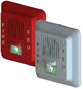
CAUTION / ATTENTION
DO NOT PAINT OR ALTER FACTORY APPLIED FINISH IN ANY WAY NE PAS PEINDRE OU MODIFIER LA FINITION ORIGINALE
ABOUT THIS MANUAL
This manual is included as a quick reference for installation. For further information on the use of this device with a FACP, please refer to the panel’s manual.
Note: This manual should be left with the owner/operator of this equipment.
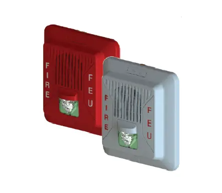
SPEAKER/SPEAKER STROBE DESCRIPTION
The SPPS-204 speaker-strobe is designed to meet UL1480/ULC S541 requirements for speakers and UL1638 /ULC S526, UL 1638A/CSA C22.2 No.205 requirements for visual notification appliances. The SPP-204 speaker is designed to meet UL1480/ULC S541 requirements for speakers.
SPPS-204 Series SPP-204 Series
Table 1 SPECIFICATION
| Operating temperature | 0⁰C to 49⁰C(32⁰F to 122⁰F) |
| Humidity range | 0% to 93% |
| Strobe flash rate | 1 Hz (1 flash per sec.)* |
| Nominal strobe voltage | Regulated 24VDC/VFWR |
| Operating voltage range | 16-33 VDC/VFWR |
| Nominal speaker voltage | 25V or 70.7Vrms |
| Speaker Size | 4” |
| Power Setting | ¼, ½, 1, 2 W |
| Speaker Frequency range | 400 -4000 Hz |
| Terminal wire gauge | 12-22 AWG |
Note: For FWR signaling use a Mircom panel.
LT-6917 Rev 1.1 Jan 22, 2021
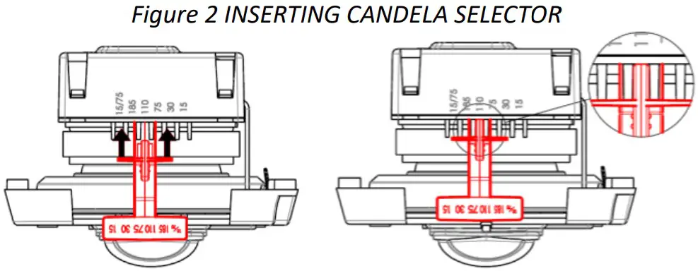
SETTING THE CANDELA (SPPS series only)
SETTING THE CANDELA (SPPS series only)
The candela can be set to 15, 30, 75, 110, 185, 15/75 for SPPS-204-25 and SPPS-204-70 models.
Note: 185cd setting is for General Signaling only
The factory default setting is 15 for SPPS-204-25/70.
- Pull out the candela selector from the device.
- Re-insert the selector tab into the notch that is labeled with the desired candela setting (when removing or inserting the candela selector, ensure to keep it straight).
Note. Select the candela setting prior to installing the device in the mounting plate
SETTING THE DIP SWITCHES
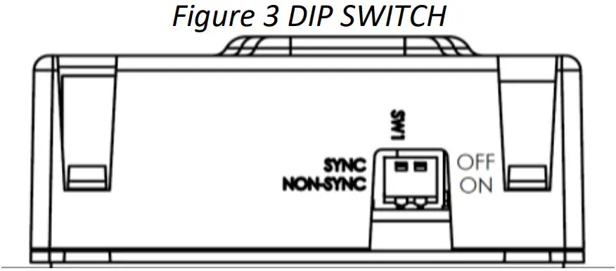
Table 2 DIP SWTICH
| DIP | OFF | ON | |
| Switch 1 | Input* | Synchronized | Regulated 24VDC /FWR(Non-sync.) |
Note: Use “SYNC” when flash synchronization is required, either through a sync module or built-in synchronization on the control unit.
Use “NON-SYNC” when the appliances do not need to be synchronized.
Note: DIP switch 1 default setting is OFF, synchronized.
Note: DIP switch 2 is not used. By default it is OFF.
WIRING
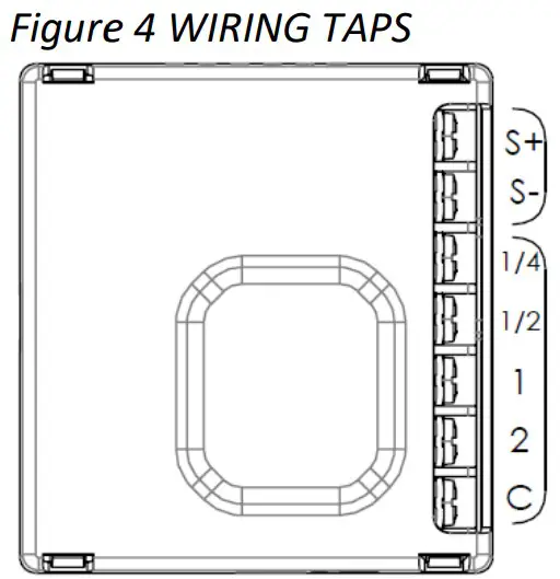
FOR MODELS WITH STROBE FEATURE, STROBE INPUT POWER (NAC)
SELECTABLE SPEAKER POWER (WATTS) Note: Connect speaker line between C and desired wattage
Note: This device should be installed as per applicable requirements of the authorities having jurisdiction.
Use the information in this document to determine the total power or current of the devices. The total power or current of the devices must not exceed the output rating of the panel. Refer to the FACP installation guide for the wire size required according to the loop length and devices power usage. For maximum strobe operating current, please refer to Table 5.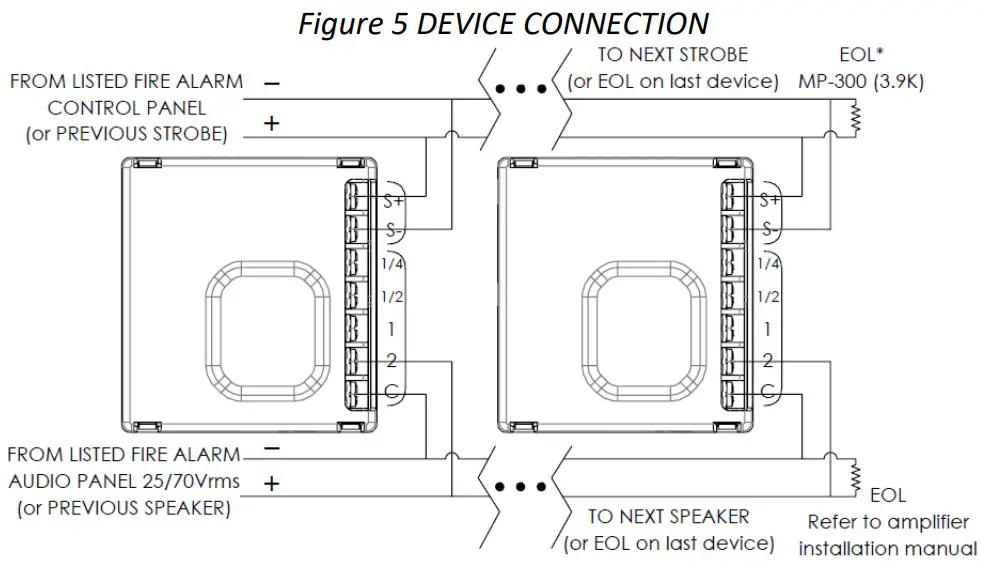
Note: When using with Mircom panel or sync module, use MP-300 (3.9K).
Note: Wiring must be in accordance with CSA C22.1, Canadian Electrical Code, Part I, Safety Standard for Electrical Installations section 32 and NFPA 70.
CAUTION
FOR ALL TERMINAL TAPS USED FOR SYSTEM SUPERVISION, DO NOT USE LOOPED WIRE UNDER TERMINALS. BREAK WIRE RUN TO PROVIDE SUPERVISION OF CONNECTIONS.
ATTENTION
NE PAS UTILISER DE FILS EN BOUCLE SOUS LES BORNES. OUVRIR LA LIGNE POUR CONFIRMER LA SUERVISION DES CONNEXIONS.
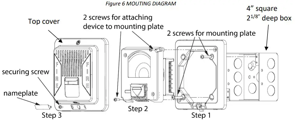
MOUNTING
MGC recommends spacing speaker strobe appliances in compliance with CAN/ULC S524 and NFPA72.
- Attach the mounting plate to the electrical box with the
- included mounting screws.
- Insert the device to the mounting plate with 2 screws.
- Attach the top cover with the included securing screw and snap the nameplate over the securing screw.
Note. Select the candela setting prior to installing the device in the mounting plate.
AUDIBLE RATINGS
Table 3 SOUND PRESSURE LEVEL OUTPUT
| SPPS-204 SERIES | ||||
| WATT Tap | UL Reverberant(dBA@10ft) | ULC Anechoic(dBA@3m) | ||
| 70 | 25 | 70 | 25 | |
| 2 | 88.4 | 88.4 | 86.5 | 85.8 |
| 1 | 86.1 | 86.3 | 83.9 | 83.5 |
| 1/2 | 83.4 | 83.6 | 81.1 | 80.7 |
| 1/4 | 80.1 | 80.3 | 77.9 | 77.5 |
| SPP-204 SERIES | ||||
| WATT Tap | UL Reverberant(dBA@10ft) | ULC Anechoic(dBA@3m) | ||
| 70 | 25 | 70 | 25 | |
| 2 | 88.5 | 88.5 | 85.5 | 86.5 |
| 1 | 86.2 | 86.5 | 81.9 | 83.1 |
| 1/2 | 83.4 | 83.7 | 79.2 | 80.3 |
| 1/4 | 80.2 | 80.5 | 76.0 | 76.9 |
Table 4 DIRECTIONAL SOUND CHARACTERISTICS
(Representative of both horizontal and vertical Axis)
| SPPS-204 SERIES | |
| ANGLE | dBA |
| +76°, -75° | -3 |
| +–°, -87° | -6 |
| ±90° | -6.3 |
| SPP-204 SERIES | |
| ANGLE | |
| ±80° | -3 |
| ±–° | -6 |
| ±90° | -5.3 |
STROBE RATINGS
Table 5 STROBE OPERATING RMS CURRENTS (mA)
| Candela | Regulated 24VDC | Regulated 24VFWR |
| 15 | 33 | 27 |
| 30 | 55 | 53 |
| 75 | 98 | 93 |
| 110 | 193 | 177 |
| 185 | 268 | 241 |
| 15/75 | 102 | 98 |
Table 6 LIGHT DISPERSION
| Degrees | % of Candela Rating | |
| Horizontal Dispersion | Vertical Dispersion,Wall to Floor | |
| ± 0 | 155 | 150 |
| ± 5 | 147 | 152 |
| ± 10 | 145 | 168 |
| ± 15 | 140 | 152 |
| ± 20 | 135 | 110 |
| ± 25 | 131 | 100 |
| ± 30 | 124 | 97 |
| ± 35 | 116 | 92 |
| ± 40 | 105 | 88 |
| ± 45 | 99 | 74 |
| ± 50 | 95 | 66 |
| ± 55 | 92 | 62 |
| ± 60 | 88 | 57 |
| ± 65 | 84 | 53 |
| ± 70 | 78 | 49 |
| ± 75 | 82 | 44 |
| ± 80 | 86 | 37 |
| ± 85 | 80 | 32 |
| ± 90 | 53 | 25 |
| Compound ±45 | 39 | |
Model Numbers
SPPS-204-25 Wall mounted speaker strobe 25V white
SPPS-204-70 Wall mounted speaker strobe 70V white
SPPS-204-25R Wall mounted speaker strobe 25V red
SPPS-204-70R Wall mounted speaker strobe 70V red
SPP-204-25 Wall mounted speaker 25V white
SPP-204-70 Wall mounted speaker 70V white
SPP-204-25R Wall mounted speaker 25V red
SPP-204-70R Wall mounted speaker 70V red
Accessories
MP-300 End of line resistor 3.9k Ohm
Support
25 Interchange way, Vaughan, Ontario. L4K 5W3
Phone: 905.660.4655;
Fax: 905.660.4113
Web: www.mircom.com


