![]()
CSPKSTR-24
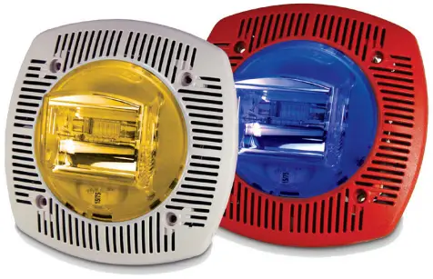
Indoor Low Profile Wall Mount Colored Speaker/Strobe Series
Features
- 24VDC fixed 15/75 candela strobe
- Lens colors available: amber, blue, green, and red
- Amber versions come with ALERT wording
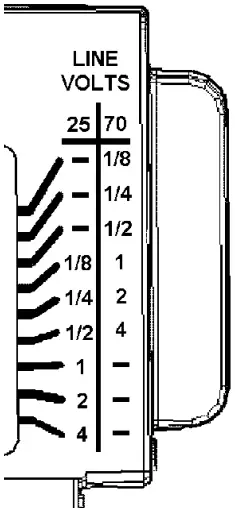
- Speaker voltage 25 or 70.7 VRMs standard, field selectable
- Field selectable power taps: 1/8W, 1/4W, 1/2W, 1W, 2W, 4W
- Xenon strobe maintains constant flash rate (1Hz)
- High quality dBA output (intelligible)
- Frequency range 400-4000 Hz
- Screw Terminals, separate in/out wiring (18-12 gauge)
- Tamperproof grill
- Faceplate available in red or off-white
- Product includes a 5 year warranty


S2657 7320-0328:0206
Application
The Potter CSPKSTR-24 is an indoor wall mount, low profile, field adjustable speaker/strobe that offers a quality speaker and visual signals. Applications include severe weather, evacuation, emergency response and many more.
Description
The CSPKSTR-24 Series offers a 24VDC, fixed 15/75 candela strobe in lens colors of amber, blue, green, and red. The CSPKSTR-24 provides a 25 or 70.7 VRMs speaker with field selectable power taps of 1/8W, 1/4W, 1/2W, 1W, 2W, or 4W. The strobes can be synchronized using the Potter AVSM Synchronization Control Module, FACP, or power supplies that produce a Gentex Synchronization Protocol.
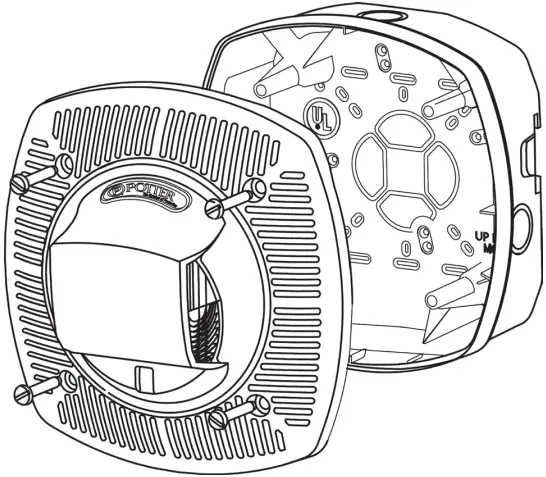
The CSPKSTR-24 can be mounted to a 4″ X 2 1/8″ deep back box without an extension ring or using Potter SPKRBB surface back box.
The CSPKSTR-24 grills are constructed of high impact textured plastic.
Product Listings
- ANSI/UL 1480 and ANSI/UL1638
- CSFM 7320-0328:0206
Product Compliance
- Americans with Disabilities Act (ADA)
- NFPA 72
- IBC/IFC/IRC
Technical Specifications
| Speaker Operating Voltage | 25VRMs or 70.7VRMs |
| Strobe Operating Voltage | 16-33VDC |
| Synchronization Module | Potter AVSM |
| Environmental Limitations | 32°F to 120°F Indoor Only |
| Unit Dimensions | 6.1” (15.494cm) square X 1.88” (4.7752cm) deep |
| Back Box | 4” X 2 1/8” deep box or Potter SPKRBB surface back box |
| Shipping Weight | 1.5 lbs. |
| CSPKSTR-24 Colored Lens Strobe Current Ratings | |
| Lens Color | 15/75CD 24VDC UL Max |
| Amber | 148mA |
| Blue | 280mA |
| Green | 360mA |
| Red | 397mA |
| Speaker dBA @ 10 ft. | ||
| Input Watts | 25 Volts | 70.7 Volts |
| 1/8 | 74.6 dBA | 73.7 dBA |
| 1/4 | 77.7 dBA | 76.7 dBA |
| 1/2 | 80.5 dBA | 79.6 dBA |
| 1 | 83.1 dBA | 82.5 dBA |
| 2 | 85.6 dBA | 85.4 dBA |
| 4 | 87.9 dBA | 87.9 dBA |
NOTE:
- Potter does not recommend using a coded or pulsing signaling circuit with any of our strobe products.
- The CSPKSTR-24 Colored Lens Series is not listed for outdoor use.
| Colored Lens Speaker/Strobes | ||
| Model Number | Description | Stock Number |
| CSPKSTR-24AR | Alert Amber Speaker/Strobe | 4890230 |
| CSPKSTR-24AW | Alert Amber Speaker/Strobe | 4890231 |
| CSPKSTR-24BR | Plain Blue Speaker/Strobe | 4890224 |
| CSPKSTR-24BW | Plain Blue Speaker/Strobe | 4890225 |
| CSPKSTR-24GR | Plain Green Speaker/Strobe | 4890226 |
| CSPKSTR-24GW | Plain Green Speaker/Strobe | 4890227 |
| CSPKSTR-24RR | Plain Red Speaker/Strobe | 4890228 |
| CSPKSTR-24RW | Plain Red Speaker/Strobe | 4890229 |
Model Designations
W = Off-White Faceplate
R = Red Faceplate
Plain units are non-returnable
Architect and Engineering Specifications
The alarm speaker shall be Potter CSPKSTR-24 Colored Lens Series or equivalent. The speaker shall be capable of producing alarm tones or voice on all 25 or 70.7 VRMs audio systems. The speaker shall provide incremental tap settings of 1/8, 1/4, 1/2, 1, 2, or 4 watts. Minimum dBA ratings at 1/4 watt shall be 76.7 dBA and at 4 watts 87.9dBA. Tap settings shall be adjustable with field selectable jumper pins. The speaker shall also have an optional visual signal capability.
The visual signal shall have a 1 Hz flash rate regardless of input voltage. All field wiring connections shall be made via separate in-out terminal connections and the speaker or speaker strobe shall be ANSI/UL listed and comply with all local, state and federal fire alarm codes/standards.
Power Tap Selection Mounting Diagram
Wiring Diagram
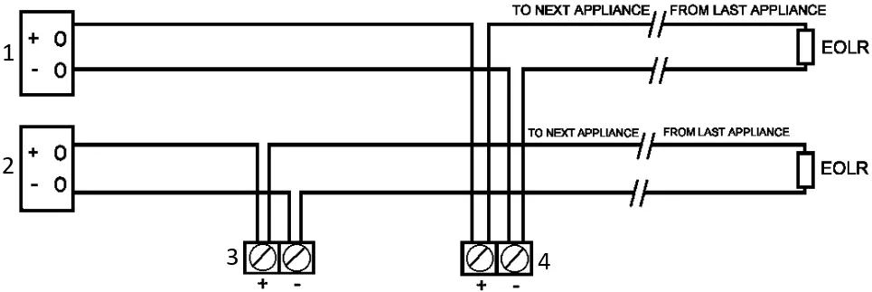
- SPEAKER 25 OR 70V SOURCE
- STROBE 24V POWER SOURCE
- STROBE (OPTIONAL)
- SPEAKER
WIRE CONDUCTIVITY
18 AWG 60
16 AWG 95
14 AWG 153
12 AWG 244
NOTE: DO NOT USE LOOPED WIRE UNDER TERMINALS. BREAK WIRE RUN TO PROVIDE SUPERVISION OF CONNECTION.
- MAX WIRE DISTANCE – PANEL VOLTAGE – DEVICE MINIMUM VOLTAGE / TOTAL CURRENT DRAW – X WIRE CONDUCTIVITY
- CAUTION: APPLIES ONLY TO REGULATED SUPPLIES.
- NOTICE: POWER IS SUPPLIED TO DEVICES WHEN CONTROL PANEL IS LATCHED.
Potter Electric Signal Company, LLC · St. Louis, MO · Tech Support: 866-956-1211 / Customer Service: 866-572-3005 · www.pottersignal.com

8830059 – REV B


