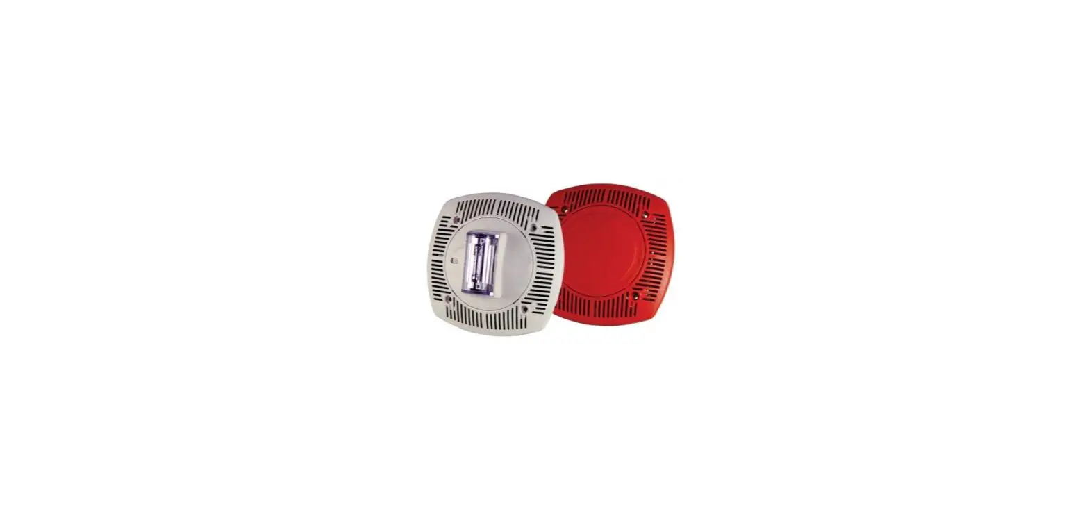

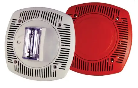
POTTER FASPKR-SPKSTR-24CLP Indoor Low Profile Speaker and Ceiling Speaker
Features
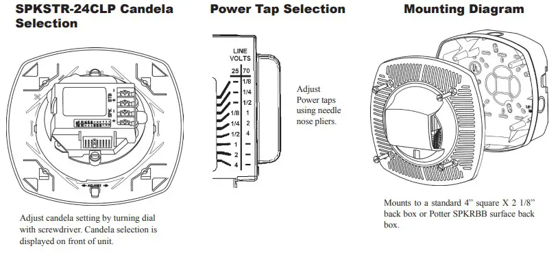
- 24VDC tamperproof selectable candela options of 15, 30, 60,75, and 110
- Speaker voltage 25 or 70.7 VRMs standard, field selectable
- Field selectable power taps: 1/8W, 1/4W, 1/2W, 1W, 2W, 4W
- High quality dBA output (intelligible)
- Frequency range 400-4000 Hz
- Screw Terminals, separate in/out wiring (18-12 gauge)
- Tamperproof grill
- Faceplate available in red or off-white
- Product includes a 5 year warranty
Application
The Potter SPKSTR-24CLP is a ceiling mount, low profile, field adjustable speaker/strobe and the FASPKR is a universal mount speaker designed to meet code requirements for audio, visual, and voice communications. The SPKSTR-24CLP Series are quality speaker products offering dependable evacuation signaling, visual alarms, or a combination of both.
Description
The SPKSTR-24CLP has high output tamperproof candela selections of 15, 30, 75, 95, and 115. The SPKSTR-24CLP and FASPKR provide a 25 or 70.7 VRMs speaker with field selectable power taps of 1/8W, 1/4W, 1/2W, 1W, 2W, or 4W. The SPKSTR-24CLP strobes can be synchronized using the Potter AVSM Synchronization Control Module, FACP, or power supplies that produce a Gentex Synchronization Protocol. The SPKSTR-24CLP and FASPKR can be mounted to a 4” X 2 1/8” deep back box without an extension ring or Potter SPKRBB surface back box. The SPKSTR-24CLP and FASPKR are constructed of high textured plastic.
Product Listings
- ANSI/UL 1480, ANSI/UL1971 and ANSI/UL 2043
CSFM 7320-0328:0208
Product Compliance
- Americans with Disabilities Act (ADA)
- NFPA 72
- IBC/IFC/IRC
Technical Specifications
| Speaker Operating Voltage | 25VRMs or 70.7VRMs |
| Strobe Operating Voltage | 16-33VDC |
| Synchronization Module | Potter AVSM |
| Environmental Limitations | 32°F to 120°F Indoor Only |
| Unit Dimensions | 6.1” (15.494cm) square X 1.88” (4.7752cm) deep |
| Back Box | 4” X 2 1/8” deep box or Potter SPKRBB surface back box |
| Shipping Weight | 1.5 lbs. |
| SPKSTR-24CLP Product Strobe Current Ratings | |||||
| Candela | 15 cd | 30 cd | 75 cd | 95 cd | 115 cd |
| 24 VDC | 72 mA | 101 mA | 167 mA | 200 mA | 214 ma |
| UL Max | 120 mA | 120 mA | 200 mA | 220 mA | 290 mA |
| Speaker dBA @ 10 ft. | ||
| Input Watts | 25 Volts | 70.7 Volts |
| 1/8 | 74.6 dBA | 73.7 dBA |
| 1/4 | 77.7 dBA | 76.7 dBA |
| 1/2 | 80.5 dBA | 79.6 dBA |
| 1 | 83.1 dBA | 82.5 dBA |
| 2 | 85.6 dBA | 85.4 dBA |
| 4 | 87.9 dBA | 87.9 dBA |
| Speaker dBA @ 10 ft. | ||
| Input Watts | 25 Volts | 70.7 Volts |
| 1/8 | 74.6 dBA | 73.7 dBA |
| 1/4 | 77.7 dBA | 76.7 dBA |
| 1/2 | 80.5 dBA | 79.6 dBA |
| 1 | 83.1 dBA | 82.5 dBA |
| 2 | 85.6 dBA | 85.4 dBA |
| 4 | 87.9 dBA | 87.9 dBA |
| Low Profile Evacuation Speakers | ||
| Model Number | Description | Stock Number |
| SpKSTR-24CLpR | Speaker/Strobe Red | 4890220 |
| SPKSTR-24CLPW | Speaker/Strobe White | 4890221 |
| SpKSTR-24CLppR | Speaker/Strobe Plain Red | 4890222 |
| SPKSTR-24CLPPW | Speaker/Strobe Plain White | 4890223 |
NOTE: Potter does not recommend using a coded or pulsing signaling circuit with any of our strobe products.
Model Designations P = Plain (No Lettering) W = Off-White Faceplate R = Red Faceplate Plain units are non-returnable
Architect and Engineering Specifications
The fire alarm speaker shall be Potter FASPKR, SPKSTR-24CLP or equivalent. The speaker shall be capable of producing alarm tones or voice on all 25 or 70.7 VRMs audio systems. The speaker shall provide incremental tap settings of 1/8, 1/4, 1/2, 1, 2, or 4 watts. Minimum dBA ratings at 1/4 watt shall be 76.7 dBA and at 4 watts 87.9dBA. Tap settings shall be adjustable with field selectable jumper pins. The speaker shall also have an optional visual signal capability. The visual signal shall have a 1 Hz flash rate regardless of input voltage. All field wiring connections shall be made via separate in-out terminal connections and the speaker or speaker strobe shall be ANSI/UL, CSFM listed and comply with all local, state and federal fire alarm codes/standards.
Wiring Diagram
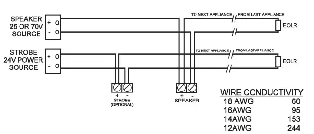
NOTE: DO NOT USE LOOPED WIRE UNDER TERMINALS. BREAK WIRE RUN TO PROVIDE SUPERVISION OF CONNECTION.
- MAX WIRE DISTANCE – – X WIRE CONDUCTIVITY
- CAUTION: APPLIES ONLY TO REGULATED SUPPLIES.
- NOTICE: POWER IS SUPPLIED TO DEVICES WHEN CONTROL PANEL IS LATCHED


 User Manual")


