POTTER SFH45-75110 Speaker Select A Strobe Combination Owner’s Manual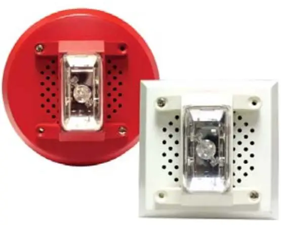
- Designed to meet or exceed NFPA/ANSI Standards and ADA accessibility guidelines
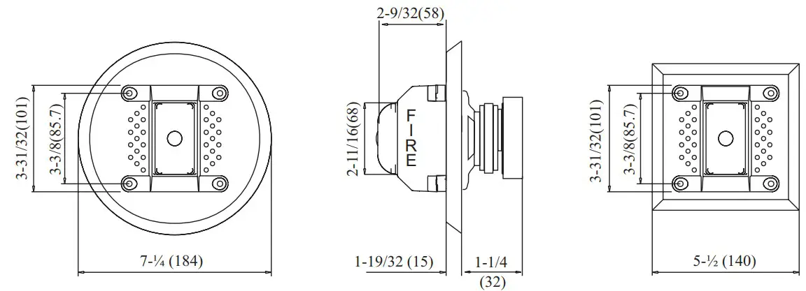
- Mounts to 4” square back box
- Field selectable taps from 2, 4, and 8 Watts
- UL Listed for wall or ceiling mount
- Available in 25V RMS and 70.7V RMS
- Screw terminals capacity up to AWG12
- Two fi eld selectable settings: 75 or 110 cd
- Tamper-proof candela selector switch
- Polarized strobes with wide operating voltage ranges using fi ltered or unfi ltered FWR input voltage
- Synchronization requires the SMD10-3A Sync Module
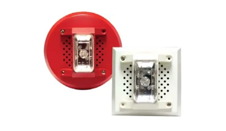
- Available in red or white housing
Amseco’s low profi le fi re alarm speakers are designed to generate attention grabbing tones and voice commands for emergency signaling
evacuation applications.
The SFH45-75110 Series are designed with the exclusive Select-A-Strobe, which features a unique candela intensity fi eld selector switch for alternating the candela output 75cd to 110cd. The strobe housing is clearly labeled with vertical “FIRE” lettering. The strobe is polarized for connecting to supervised fi re alarm circuits. It is also designed with a xenon fl ash tube and provides a candela intensity fi eld selector switch for maximum performance. These highly effi cient low profi le speakers are available with fi eld selectable taps from 2 – 8 Watts. The speakers are available in two input voltage models of 25 and 70.7V RMS.
The SFH45-75110 can be synchronized by using the SMD10-3A Sync Module to comply with NFPA recommendations concerning photosensitive epilepsy when installing two or more visual appliances within the fi eld of view. The strobe signals are listed for indoor use, wall mount, under UL 1971 standard.
Ordering Information
| Model Number | Stock Number | Speaker Voltage (V RMS) | Strobe Voltage (VDC) | Strobe Candela | Selectable Wattage | Flash Rate (Per Minute) | Grille Typ | Grille Color |
| SFH45-75110R-25S | 4650014 | 25 | 24 | 75 or 110 | 2,4,8 | 60 | Square | Red |
| SFH45-75110W-25S | 4650018 | 25 | 24 | 75 or 110 | 2,4,8 | 60 | Square | White |
| SFH45-75110R-25R | 4650013 | 25 | 24 | 75 or 110 | 2,4,8 | 60 | Round | Red |
| SFH45-75110W-25R | 4650017 | 25 | 24 | 75 or 110 | 2,4,8 | 60 | Round | White |
| SFH45-75110R-70S | 4650016 | 70.7 | 24 | 75 or 110 | 2,4,8 | 60 | Square | White |
| SFH45-75110W-70S | 4650020 | 70.7 | 24 | 75 or 110 | 2,4,8 | 60 | Square | Red |
| SFH45-75110R-70R | 4650015 | 70.7 | 24 | 75 or 110 | 2,4,8 | 60 | Square | White |
| SFH45-75110W-70R | 4650019 | 70.7 | 24 | 75 or 110 | 2,4,8 | 60 | Round | Red |
Engineering Specifi cations
The speaker and visual alarm indicating appliance shall be Amseco model SFH45-75110 or equivalent device, and shall be listed under UL 1480 standard for audible and voice communications approved for fi re protective service. The fi re alarm speaker shall be capable of reproducing alarm tones or voice commands on 25V RMS or 70.7V RMS. Speakers shall provide incremental tap settings of 2, 4, and 8 Watts, and have a frequency range of 400 to 4000 Hz. They shall produce a UL sound pressure level at 10 feet up to 96dBA. The strobe shall be listed under UL 1971 standard for signaling devices for the hearing impaired and shall be approved for fi re protection service. The candela ouput shall be fi eld selectable, having a dual setting of 75cd or 110cd intensity output. The signaling strobe shall operate on 24V DC from a non-coded regulated
DC supply or full-wave rectifi ed, unfiltered supply. The strobe shall be designed to produce one signal fl ash per second with continuously applied minimum voltage. The speaker is capable of ceiling or wall mounting to a 4” x 4” deep back box. When strobe synchronization is required, the strobe shall be compatible with the Amseco SMD10-3A (daisy chain) or other source of Amseco sync protocol. Audible and signaling devices shall be installed in accordance with current NFPA guidelines
Dimensions: inches (mm)
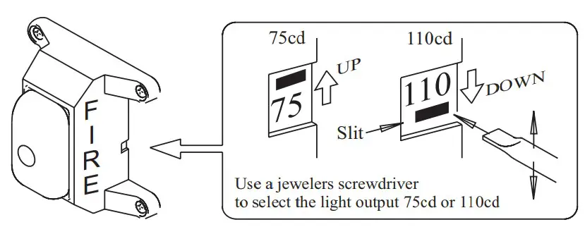
Installation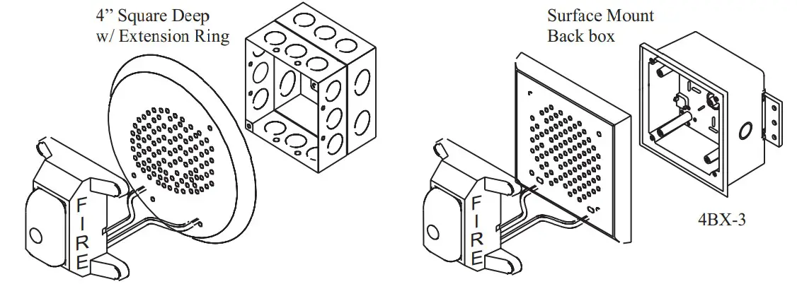
Wiring Diagram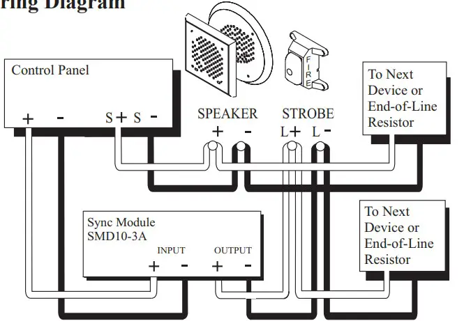
| UL Required Min. Light Output | Horizontal | Vertical | |||
| DEGREES | 75cd | 110cd | 75cd | 110cd | |
| 0 | 75.00 | 110.00 | 75.00 | 110.00 | |
| 5-25 | 67.50 | 99.00 | 67.50 | 99.00 | |
| 30 | 56.25 | 82.50 | 67.50 | 99.00 | |
| 35 | 56.25 | 82.50 | 48.75 | 71.50 | |
| 40 | 56.25 | 82.50 | 34.50 | 50.60 | |
| 45 | 56.25 | 82.50 | 25.50 | 37.40 | |
| 50 | 41.25 | 60.50 | 20.25 | 29.70 | |
| 55 | 33.75 | 49.50 | 16.50 | 24.20 | |
| 60 | 30.00 | 44.00 | 13.50 | 19.80 | |
| 65 | 26.25 | 38.50 | 12.00 | 17.60 | |
| 70 | 26.25 | 38.50 | 11.25 | 16.50 | |
| 75 | 22.50 | 33.00 | 9.75 | 14.30 | |
| 80 | 22.50 | 33.00 | 9.00 | 13.20 | |
| 85-90 | 18.75 | 27.50 | 9.00 | 13.20 | |
| Compound 45 | 18.00 | 26.40 | 18.00 | 26.40 | |
| Speaker Specifi cation | Rated Input Voltage (V RMS) 25V 70.7V Input Power (Watts) 2 | 25V | 70.7V | ||||
| Input Power (Watts) | 2W | 4W | 8W | 2W | 4W | 8W | |
| Impedance (Ohms) | 310 | 156 | 78 | 2.5K | 1250 | 620 | |
| Sound Pressure (dB/10ft | 87 | 90 | 90 | 87 | 87 | 90 | |
| Frequency Response (Hz) | 400-4000 | ||||||
| Low Frequency Cut-off (Hz) | 200 | ||||||
| Operating Temperature Range | 14°F – 140°F (-10°C – 60°C) | ||||||
| Under CAN/ ULC 526 | ULC Current (mA) | |
| Regulated 24V DC | Regulated 24V FWR | |
| 75cd | 264 | 596 |
| 110cd | 324 | 732 |
| Strobe Ligh | Max. RMS Operating Current (mA | |
| Regulated 24V DC (Typical) | Regulated 24V FWR (Typical) | |
| 75cd | 260 (190) | 368 (249 |
| 110cd | 387 (250) | 489 (320) |
![]() Warning
Warning
High voltage may be present inside the light assembly even though power is not connected. If access to the component board is required, the capacitor must be discharged by touching a wire to both ends of the fl ashtube. DO NOT attempt to touch or remove the assembly until the capacitor has been discharged. Indoor use only.


