
POTTER SSC25-70-177 Speaker-Strobe Combination
- ADA/NFPA/ANSI compliant
- Screw terminal capacity up to AWG #12
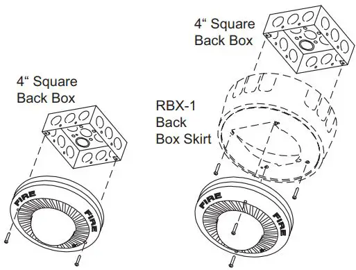
- RBX-1 back box skirt for surface mount (optional)
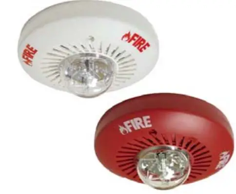
- Available in red or white housing
- All models mount to 4” back box
- Speaker is UL 1480 listed for fi re protective service
- Speaker fi eld selectable wattage from ¼, ½, 1, and 2 Watts
- Speaker is available in 25V RMS or 70.7V RMS models
- Speaker frequency range 400 to 4000 Hz
- Speaker has integral blocking capacitor for line supervision
- Strobe is UL listed for ceiling and wall mount
- Fixed 177cd output
- Strobe is operable with 24V regulated DC or FWR (16-33V)
- Polarized strobes with wide operating voltage range using fi ltered DC or unfi ltered FWR input voltage
- Minimum one flash per second (1Hz)
- Selectable light output candela: low, medium, or high
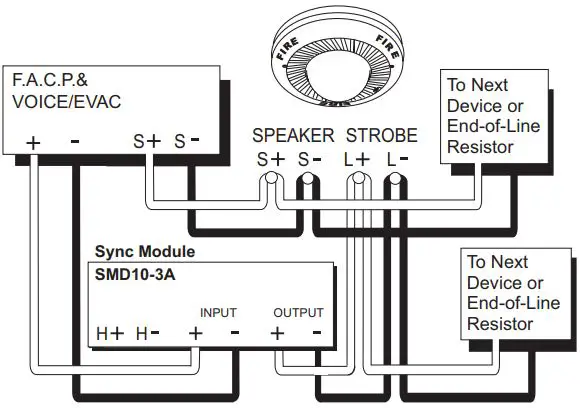
- Synchronization requires SMD10-3A Sync Module
Amseco’s ceiling and wall mount fi re alarm Speaker/Strobe Series are designed to generate attention grabbing tones and voice commands for emergency signaling evacuation applications. These highly effi cient, low profi le speakers are available with fi eld selectable taps ¼, ½, 1, and 2 Watts. The speakers are available in two input voltage models, 25V RMS and 70.7V RMS and can be installed on a standard 4” square back box. The strobe features a candela output of 177cd, and is polarized for connecting to supervise fi re alarm circuits. The strobe housing is clearly labeled with “FIRE” lettering and is designed with a xenon fl ash tube and provides a candela intensity fi eld selector switch for maximum performance. The series can be synchronized by using the SMD10-3A (daisy chain) Sync Module to comply with NFPA recommendations concerning photosensitive epilepsy when installing two or more visual appliances within the fi eld of view. The strobe signals are designed for non-sleeping areas and are listed for indoor use.
Ordering Information
| Model Number | Stock Number | Housing Color | Speaker Voltage | Input Voltage | Operating Voltage Range | Fixed Strobe Output | Flash Rate | Mounting Type | Operating Temperature Range |
| SSC25-177R | 4660005 | Red | 25V | ||||||
| SSC25-177W | 4660006 | White | RMS | Regulated 24V DC/WR | 16-33V DC 16-33V FWR | 177cd | 60 times/ min. | Ceiling and Wall | 32°F – 120°F (0°C – 49°C) |
| SSC70-177R | 4660009 | Red | 70.7V | ||||||
| SSC70-177W | 4660010 | White | RMS |
Engineering Specifi cations
The speaker and visual alarm indicating appliance shall be Amseco Model SSC25-177 or SSC70-177 or equivalent device. The speaker shall be listed under UL 1480 standards for audible and voice communications and shall be approved for fi re protective service. The fi re alarm speaker shall be capable of reproducing alarm tones or voice commands on 25V RMS or 70.7V RMS. Speakers shall provide incremental tap settings of ¼, ½, 1, or 2 Watts. They shall have a frequency range of 400 to 4000 Hz and produce UL sound pressure level at 10 feet up to 84dBA. The speaker shall be approved for fi re alarm signaling use. The strobe shall be listed under UL 1971 standard for signaling devices for the hearing impaired and shall be approved for fi re protection service. The candela ouput shall be fi eld selectable, having three settings of 30cd, 75cd, or 110cd. The signaling strobe shall operate on 24V DC from a non-coded, regulated DC supply or full-wave rectifi ed, unfi ltered supply. The strobe shall be designed to produce one signal fl ash per second with continuously applied minimum voltage. The strobe may have a SPC-1 universal back mounting plate, capable of ceiling or wall mounting to a back box. When strobe synchronization is required, the strobe shall be compatible with the Amseco SMD10-3A (daisy chain) or other source of Amseco sync protocol. Signaling devices shall be installed in sleeping areas in accordance with current NFPA guidelines.
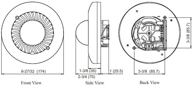
Dimensions: inches (mm)
| Speaker Specifications | ||||||||
| Voltage | 25V RMS | 70.7V RMS | ||||||
| Input Power (Watts) | ¼ | ½ | 1 | 2 | ¼ | ½ | 1 | 2 |
| Impedance (k Ohms) | 2.5 | 1.25 | 0.62 | 0.31 | 20 | 10 | 5 | 2.5 |
| Sound Pressure (dB/10ft) | 75 | 78 | 81 | 84 | 75 | 78 | 81 | 84 |
| Frequency Response | 400 – 4000 Hz | |||||||
| Low Frequency Cut-Off | 200 Hz | |||||||
| Strobe Light | Maximum RMS Operating Current (mA) | |
| Regulated 24V DC (Typical) | Regulated 24V FWR (Typical) | |
| 177cd | 347 (240) | 437 (345) |
| UL Required Minimum Light Output | Ceiling Mount | |
| 177 cd | ||
| DEGREES | 0 | 177.00 |
| 5-25 | 159.30 | |
| 30-45 | 132.75 | |
| 50 | 97.35 | |
| 55 | 79.65 | |
| 60 | 70.80 | |
| 65-70 | 61.95 | |
| 75-80 | 53.10 | |
| 85-90 | 44.25 | |
| Compound 45 | 42.48 | |
Wiring Diagram
Mounting
Potter Electric Signal Company • 2081 Craig Road, St. Louis, MO, 63146-4161 • Phone: 800-325-3936/Canada 888-882-1833 • www.pottersignal.com


