
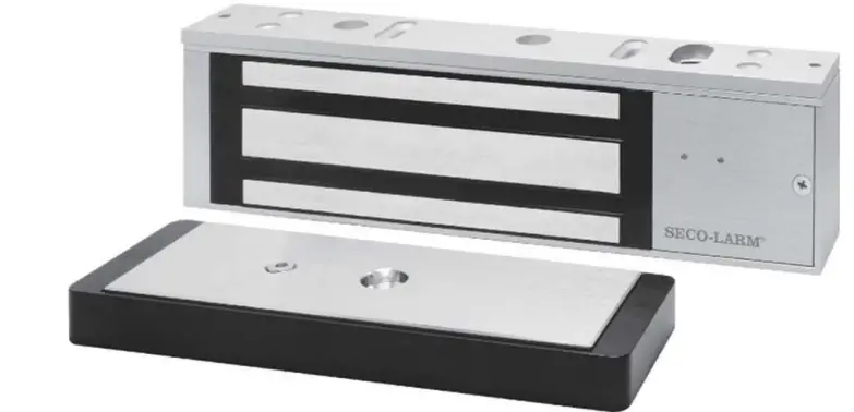
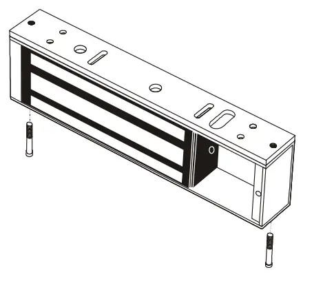
 SECO-LARM E-941Sx-600DPSQ Electromagnetic Locks
 Parts List
 Parts List
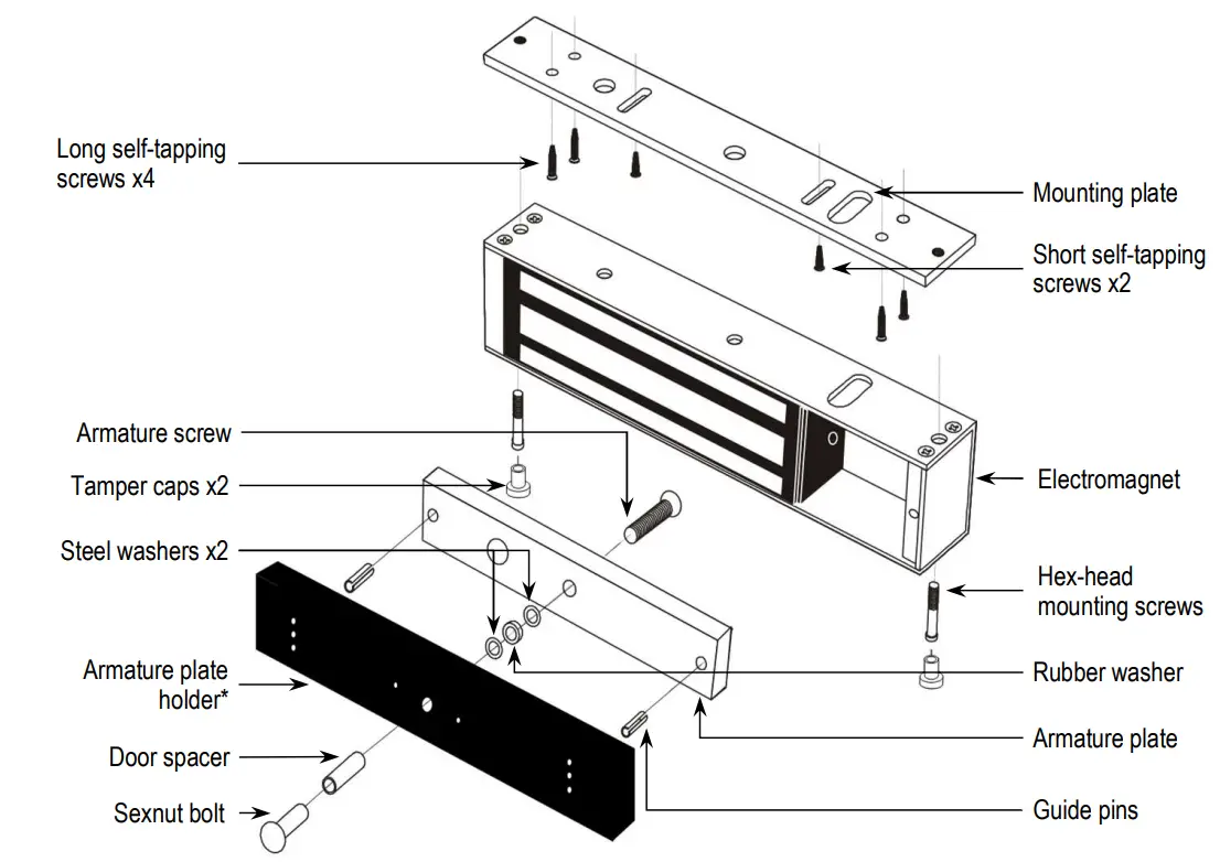
- 1x Electromagnet
- 2x Steel washers
- 2x Guide pins
- 2x Tamper caps
- 1x Armature plate
- 1x Rubber washer
- 1x Door spacer
- 2x Hex wrenches
- 2x Short self-tapping screws
- 4x Long self-tapping screws
- 2x Hex-head mounting screws
- 1x Armature plate holder*
- 1x Armature screw
- 1x Sexnut bolt
- 1x Mounting plate
- 1x Manual
Specifications
| Holding Force | 600-lb | 1,200-lb. | |
| Operating voltage | 12/24 VDC | ||
| Current draw | 12VDC | 500mA | |
| 24VDC | 250mA | ||
| Bond sensor | SPDT relay, 3A@12VDC | ||
| Door position sensor | Reed switch, 0.2A@12VDC | ||
| Operating temperature | 32°~120° F (0°~49° C) | ||
| Dimensions | Magnet | 913/16″x111/16″x1″ (250x43x25 mm) | 101/2″x27/16″x19/16″ (267x62x40 mm) |
| Armature | 71/4″x11/2″x1/2″ (185x38x12 mm) | 71/4″x27/16″x5/8″ (184x62x16 mm) | |
| Destructive attack | Level I | ||
| Line Security | Level I | ||
| Standby power | Level I | ||
| Endurance | Level IV | ||
Overview Installation Applications
 Installation Applications
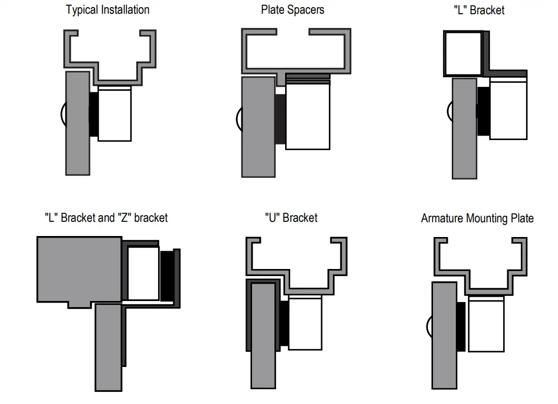
- When mounting the electromagnet, it may be necessary to use a “Z” and “L” bracket, an “L” bracket, a “U” bracket, and/or plate spacers, depending on the location and the type of door and frame.
- Use the diagram below to help decide whether or not an optional bracket will be necessary for installation.

Installation Notes
- Read this installation manual thoroughly. A clear understanding of the product and this manual will make installation much easier.
- The electromagnetic lock is designed for indoor use ONLY.
- The most suitable mounting location for the electromagnetic lock may require the use of additional SECO-LARM accessories such as Z-brackets, L-brackets, and/or spacer plates. Please see the diagram on page 3 to decide if a particular application requires any mounting accessories.
- Do not run power wires and signal wires in the same conduit as this may cause interference.
- Do not install a diode in parallel with the electromagnetic lock as this may cause a delay when releasing the door as well as cause residual magnetism.
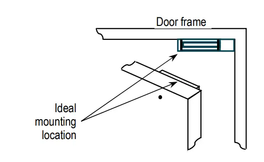
- The best location to install the electromagnetic lock is on the inside of the door that is being secured with the wiring concealed in the frame to prevent tampering with the unit.
- The minimum permissible wire size to be used shall not be less than 22AWG.
Installation
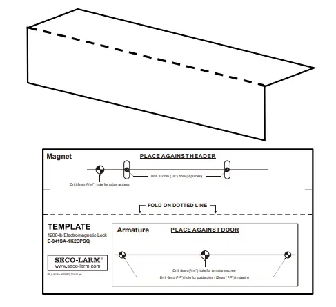
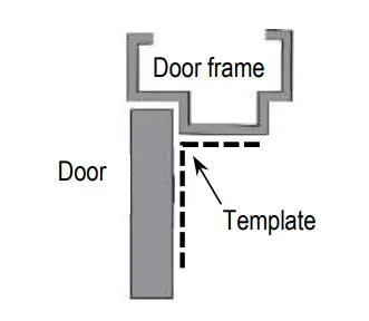
- Fold the mounting template along the dotted line to form a 90-degree angle.

- Close the door. Find a mounting location on the door frame near the upper free-moving corner of the door, or as close as possible to the upper corner of the door frame opposite the hinges.

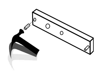
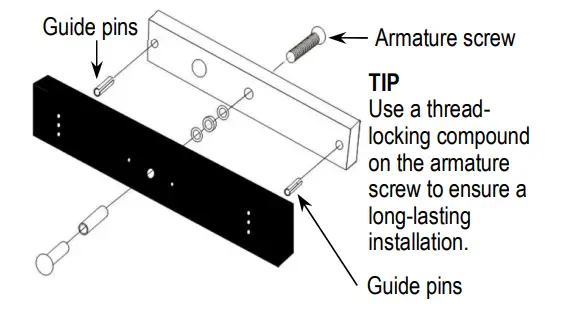
- Use a hammer to lightly tap the two guide pins into the guide pin holes on the armature plate.

- Place the template against the door and frame. Mark where the holes are to be drilled.

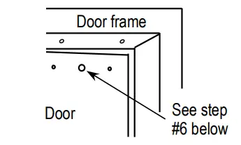
- Drill holes in the frame and the door as shown on the template and in step #6 below. The smaller holes on the door should not go all the way through.

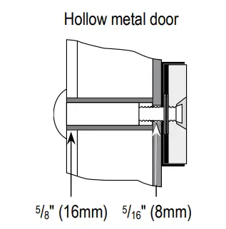
- Depending on the type of door being protected, drill holes according to the diagrams below:
 Drill a 5/16″ hole (8mm) diameter hole through the armature-plate side of the door for the armature screw. Then drill a 5/8″ (16mm) diameter hole for the sexnut screw on the opposite side of the door.
  Drill a 1/4″ hole (6.8mm) diameter and 1″ (25mm) deep hole, tap for M8x1.25 thread.
  Drill a 5/16″ hole (8mm) diameter hole in the door for the armature screw and drill a 1/2″ (12.7mm) diameter and 1″ (25mm) deep hole from the opposite side for the sexnut screw
 - Put a rubber washer between the two metal washers and place them over the armature screw between the armature plate and the armature plate holder. This allows the plate to pivot around the screw to compensate for door misalignment.

- Tighten the armature screw enough so that the armature plate can withstand a break-in attempt, but loose enough so that the armature plate can pivot slightly. Make sure the anti-spin guide pins are in the two guide pin holes.

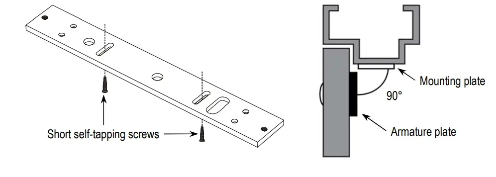
- Screw the two short self-tapping screws through the mounting plate’s slotted holes, but do not over-tighten them. Keeping them loose will allow for adjustment of the plate so that the long edge of the mounting plate and the armature plate are parallel. See the diagram below.

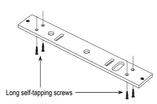
- Once the mounting plate position is correct, use the four long self-tapping screws to permanently mount the mounting plate.

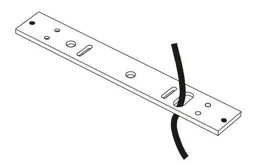
- Drill the cable access hole. Run the wiring through the cable access hole in the mounting plate and through the hole in the door frame.

- Remove the cover from the front of the electromagnet. Run the power leads through the large cable access hole.

- Push the electromagnet against the mounting plate so the electromagnet ends are flush with the ends of the mounting plate. Use the Allen wrench to screw the hex-head mounting screws through the bottom of the electromagnet into the mounting bracket.

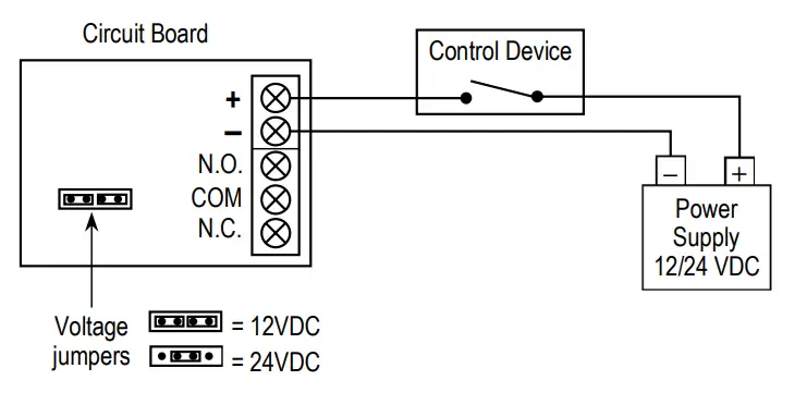
- Cut the wires so they are long enough to connect with the terminal block. Set the voltage using the selection jumpers based on your input voltage.
 NOTES
NOTES - Failure to correctly set the input voltage may cause damage to the lock.
- connect switching devices like push-to-exit switches between the power source and the positive terminal on the lock. Connecting switching devices to the negative terminal may cause a delay in unlocking.
- Connect the power and other wires according to the wiring diagram on page 7. Test the unit. Then replace the front cover and install the hex-head tamper caps (x2).
NOTE: This should be the very last step after all steps are confirmed, since once the tamper caps are in place, they are very difficult to remove.
 Drill a 5/16″ hole (8mm) diameter hole through the armature-plate side of the door for the armature screw. Then drill a 5/8″ (16mm) diameter hole for the sexnut screw on the opposite side of the door.
 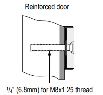 Drill a 1/4″ hole (6.8mm) diameter and 1″ (25mm) deep hole, tap for M8x1.25 thread.
 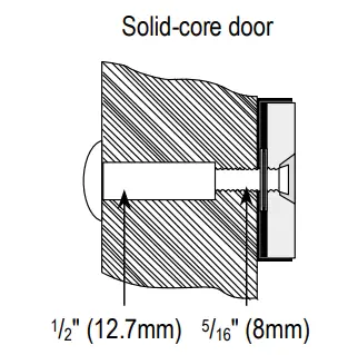 Drill a 5/16″ hole (8mm) diameter hole in the door for the armature screw and drill a 1/2″ (12.7mm) diameter and 1″ (25mm) deep hole from the opposite side for the sexnut screw
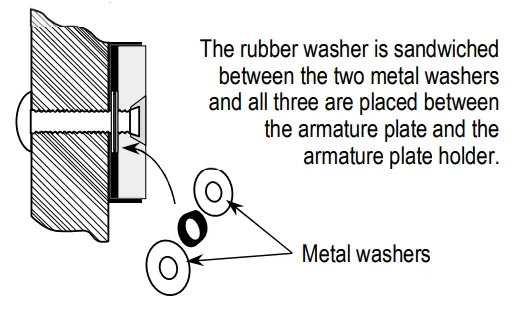

 NOTES
NOTES 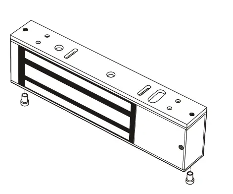
Wiring Diagram
NOTES
Connect switching devices like push-to-exit switches between the power source and the positive terminal of the lock. Connecting them to the negative terminal may cause a delay in unlocking.
Maximum Distance from Power Source
For a complete chart, visit www.seco-larm.com
12VDC Minimum Wire Gauge
| Wire Length | 25ft | 50ft | 75ft | 100ft | 150ft | 200ft | 250ft | 300ft | 400ft | 500ft | 1,000ft |
| Wire Gauge@500mA | 20 | 18 | 18 | 18 | 16 | 14 | 14 | 12 | 10 | — | — |
24VDC Minimum Wire Gauge
| BV | 25ft | 50ft | 75ft | 100ft | 150ft | 200ft | 250ft | 300ft | 400ft | 500ft | 1,000ft |
| Wire Gauge@250mA | 22 | 22 | 22 | 20 | 18 | 18 | 16 | 16 | 14 | 14 | 14 |
Wiring Diagram
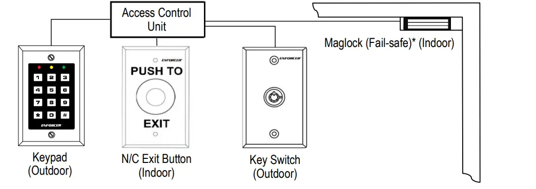
*A fail-safe lock unlocks when power is lost so that, in case of an emergency such as a fire in the building, the fail-safe lock will automatically unlock allowing personnel to escape quickly.
NOTE: All field wiring must be within the protected area.
Troubleshooting
Doors lock, but can easily be forced open
- Make sure the electromagnet and armature plates are properly aligned.
- Make sure the contact surfaces of the electromagnet and armature plates are clean and free from rust.
- Check the power leads with a meter, and make sure 12VDC or 24VDC is present.
- Make sure the rubber washer is installed and free from damage.
Delay in door releasing
- The electromagnet is fitted with a metal oxide varistor to prevent interference, so do not install a second diode.
- Ensure that the control device is connected between the power source and the positive terminal of the lock
IMPORTANT WARNING: Incorrect mounting which leads to exposure to rain or moisture inside the enclosure could cause a dangerous electric shock, damage the device, and void the warranty. Users and installers are responsible for ensuring that this product is properly installed and sealed.
IMPORTANT: Users and installers of this product are responsible for ensuring that the installation and configuration of this product complies with all national, state, and local laws and codes. SECO-LARM will not be held responsible for the use of this product in violation of any current laws or codes.
California Proposition 65 Warning: These products may contain chemicals which are known to the State of California to cause cancer and birth defects or other reproductive harm. For more information, go to www.P65Warnings.ca.gov.
LIMITED LIFETIME WARRANTY
This SECO-LARM product is warranted against defects in material and workmanship while used in normal service for the lifetime of the product. SECO-LARM’s obligation is limited to the repair or replacement of any defective part if the unit is returned, transportation prepaid, to SECO-LARM. This Warranty is void if damage is caused by or attributed to acts of God, physical or electrical misuse or abuse, neglect, repair or alteration, improper or abnormal usage, or faulty installation, or if for any other reason SECO-LARM determines that such equipment is not operating properly as a result of causes other than defects in material and workmanship. The sole obligation of SECO-LARM and the purchaser’s exclusive remedy, shall be limited to the replacement or repair only, at SECO-LARM’s option. In no event shall SECO-LARM be liable for any special, collateral, incidental, or consequential personal or property damage of any kind to the purchaser or anyone else. For all other countries, the warranty is 1 (one) year.
NOTICE: The SECO-LARM policy is one of continual development and improvement. For that reason, SECO-LARM reserves the right to change specifications without notice. SECO-LARM is also not responsible for misprints. All trademarks are the property off SECO-LARM U.S.A., Inc. or their respective owners. Copyright © 2021 SECO-LARM U.S.A., Inc. All rights reserved.


