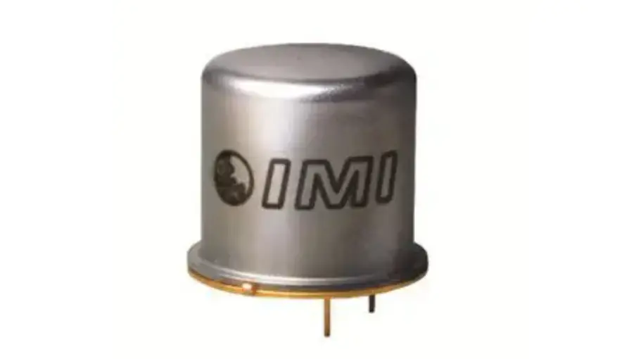
IMI SENSORS 66102ANZ1 ICP Low-Profile TO-5 Accelerometer
Repair and Maintenance
PCB guarantees Total Customer Satisfaction through its “Lifetime Warranty Plus” on all Platinum Stock Products sold by PCB and through its limited warranties on all other PCB Stock, Standard and Special products. Due to the sophisticated nature of our sensors and associated instrumentation, field servicing and repair is not recommended and, if attempted, will void the factory warranty.
Beyond routine calibration and battery replacements where applicable, our products require no user maintenance. Clean electrical connectors, housings, and mounting surfaces with solutions and techniques that will not harm the material of construction. Observe caution when using liquids near devices that are not hermetically sealed. Such devices should only be wiped with a dampened cloth—never saturated or submerged.
In the event that equipment becomes damaged or ceases to operate, our Application Engineers are here to support your troubleshooting efforts 24 hours a day, 7 days a week. Call or email with model and serial number as well as a brief description of the problem.
Calibration
Routine calibration of sensors and associated instrumentation is necessary to maintain measurement accuracy. We recommend calibrating on an annual basis, after exposure to any extreme environmental influence, or prior to any critical test.
PCB Piezotronics is an ISO-9001 certified company whose calibration services are accredited by A2LA to ISO/IEC 17025, with full traceability to SI through N.I.S.T. In addition to our standard calibration services, we also offer specialized tests, including: sensitivity at elevated or cryogenic temperatures, phase response, extended high or low frequency response, extended range, leak testing, hydrostatic pressure testing, and others. For more information, contact your local PCB Piezotronics distributor, sales representative, or factory customer service representative.
Returning Equipment
If factory repair is required, our representatives will provide you with a Return Material Authorization (RMA) number, which we use to reference any information you have already provided and expedite the repair process. This number should be clearly marked on the outside of all returned package(s) and on any packing list(s) accompanying the shipment.
Contact Information
- PCB Piezotronics, Inc.
- 3425 Walden Ave.
- Depew, NY14043 USA
- Toll-free: (800) 828-8840
- 24-hour SensorLine: (716) 684-0001
- General inquiries: [email protected]
- Repair inquiries: [email protected]
For a complete list of distributors, global offices and sales representatives, visit our website, www.pcb.com.
Safety Considerations
This product is intended for use by qualified personnel who recognize shock hazards and are familiar with the precautions required to avoid injury. While our equipment is designed with user safety in mind, the protection provided by the equipment may be impaired if equipment is used in a manner not specified by this manual.
Discontinue use and contact our 24-Hour Sensorline if:
- Assistance is needed to safely operate equipment
- Damage is visible or suspected
- Equipment fails or malfunctions
For complete equipment ratings, refer to the enclosed specification sheet for your product.
Definition of Terms and Symbols
The following symbols may be used in this manual:
 DANGER
Indicates an immediate hazardous situation, which, if not avoided, may result in death or serious injury. CAUTION
Refers to hazards that could damage the instrument. NOTE
NOTE
Indicates tips, recommendations and important information. The notes simplify processes and contain additional information on particular operating steps.
 DANGER
 NOTE
NOTEThe following symbols may be found on the equipment described in this manual:
 This symbol on the unit indicates that high voltage may be present. Use standard safety precautions to avoid personal contact with this voltage.
- This symbol on the unit indicates that the user should refer to the operating instructions located in the manual.
 This symbol indicates safety, earth ground.
 This symbol indicates safety, earth ground.
PCB Industrial Monitoring and Measuring Equipment – China RoHS 2 Disclosure Table
| Component Name | Hazardous Substances | |||||
| Lead (Pb) | Mercury (Hg) | Cadmium (Cd) | Chromium VI Compounds (Cr(VI)) | Polybrominated Biphenyls (PBB) | Polybrominated Diphenyl Ethers (PBDE) | |
| Housing | O | O | O | O | O | O |
| PCB Board | X | O | O | O | O | O |
| Electrical Connectors | O | O | O | O | O | O |
| Piezoelectric Crystals | X | O | O | O | O | O |
| Epoxy | O | O | O | O | O | O |
| Teflon | O | O | O | O | O | O |
| Electronics | O | O | O | O | O | O |
| Thick Film Substrate | O | O | X | O | O | O |
| Wires | O | O | O | O | O | O |
| Cables | X | O | O | O | O | O |
| Plastic | O | O | O | O | O | O |
| Solder | X | O | O | O | O | O |
| Copper Alloy/Brass | X | O | O | O | O | O |
| This table is prepared in accordance with the provisions of SJ/T 11364. O: Indicates that said hazardous substance contained in all of the homogeneous materials for this part is below the limit requirement of GB/T 26572. X: Indicates that said hazardous substance contained in at least one of the homogeneous materials for this part is above the limit requirement of GB/T 26572. Lead is present due to allowed exemption in Annex III or Annex IV of the European RoHS Directive 2011/65/EU. | ||||||
| Model Number 66102ANZ1 | ICP® LOW-PROFILE TO-5 ACCELEROMETER | Revision: B ECN #: 49711 | |||||
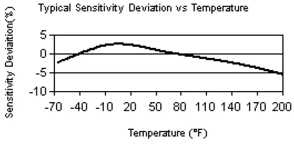
| Performance ENGLISH SI Sensitivity(± 20 %) 10 mV/g 1.02 mV/(m/s²) [6][1] Measurement Range ± 500 g ± 5,000 m/s² Frequency Range(± 3 dB) 0.5 to 10 kHz 0.5 to 10 kHz [3][7] Resonant Frequency > 25 kHz > 25 kHz [7] Broadband Resolution 0.0018 g rms 0.017658 m/s² rms [4] Non-Linearity ≤ 1 % ≤ 1 % [2] Transverse Sensitivity ≤ 7 % ≤ 7 % Environmental Overload Limit(Shock) 5,000 g pk 49k m/s² pk Temperature Range(Operating) -65 to +185 °F -54 to +85 °C Temperature Response See Graph See Graph [4] Electrical Settling Time(within 1% of bias) ≤ 2 sec ≤ 2 sec Discharge Time Constant ≥ 0.3 sec ≥ 0.3 secExcitation Voltage 18 to 28 VDC 18 to 28 VDC Constant Current Excitation 2 to 20 mA 2 to 20 mA Output Impedance < 100 Ohm < 100 Ohm Output Bias Voltage 8 to 12 VDC 8 to 12 VDC Spectral Noise(10 Hz) 19 µg/√Hz 186.4 (µm/sec2)/√Hz [4] Spectral Noise(100 Hz) 8 µg/√Hz 78.5 (µm/sec2)/√Hz [4] Spectral Noise(1 kHz) 5 µg/√Hz 49.1 (µm/sec2)/√Hz [4] Physical Size – Lip Diameter 0.36 in 9.1 mm Size – Height 0.26 in 6.6 mm Weight 0.08 oz 2.2 gm Mounting Adhesive/Solder Adhesive/Solder Sensing Elemen Ceramic Ceramic Sensing Geometry Shear Shear Housing Material Stainless Steel Stainless Steel Sealing Welded Hermetic Welded Hermetic Electrical Connector Header Pins Header Pins Electrical Connection Position Bottom Bottom Electrical Connections(Pin 1) Signal / Power Signal / Power Electrical Connections(Pin 2) Neg (-) Ground Neg (-) Ground Electrical Connections(Pin 3) No Connection No Connection | OPTIONAL VERSIONS Optional versions have identical specifications and accessories as listed for the standard model except where noted below. More than one option may be used. | ||||||
| NOTES: [1] Conversion Factor 1g = 9.81 m/s². [2] Zero-based, least-squares, straight line method. [3] The high frequency tolerance is accurate within ±10% of the specified frequency. [4]Typical. [5]See PCB Declaration of Conformance PS023 or PS060 for details. [6]Negative output along Z-axis (in upward direction when pin mounted). [7]Performance depends on mounting | |||||||
 | SUPPLIED ACCESSORIES: Model ICS-2 NIST-traceable single-point amplitude response calibration at 6000 cpm (100 Hz) for each axis (1) | ||||||
| Entered: LK | Engineer: YHK | Sales: MC | Approved: NJF | Spec Number: | |||
| Date: 07/03/2019 | Date: 07/03/2019 | Date: 07/03/2019 | Date: 07/03/2019 | 47360 | |||
| All specifications are at room temperature unless otherwise specified. In the interest of constant product improvement, we reserve the right to change specifications without notice. ICP® is a registered trademark of PCB Piezotronics, Inc. | 3425 Walden Avenue, Depew, NY 14043 | Phone: 800-959-4464 Fax: 716-684-3823 E-M ail: [email protected] | |||||
References
 PCB Piezotronics | Sensors to measure vibration, acoustics, force, pressure, load, strain, shock & torque
-
PCB Piezotronics | Sensors to measure vibration, acoustics, force, pressure, load, strain, shock & torque
-
PCB Piezotronics | Sensors to measure vibration, acoustics, force, pressure, load, strain, shock & torque


