![]() AC-43 MEMS Accelerometer
AC-43 MEMS Accelerometer
User Manual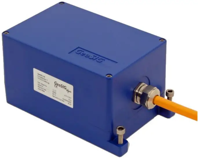
| Author: | Serge Rudaz |
| Checked: | Talhan Biro |
| Approved: | Johannes Grob |
| Distribution: | GeoSIG Ltd (1), Customer on request |
DOCUMENT REVISION
| Version | Date | Modification | Prepared | Checked | Released |
| 1 | 12.2.2007 | Adapted to new sensor housing File name and title change | SR | TB | |
| 2 | 25.02.2008 | Updated with DH version. | SR | TB | |
| 3 | 23.09.2013 | Axis orientation | JLT | MAE | |
| 4 | 06.06.2014 | New logo | VAG | ||
| 5 | 07.05.2019 | Mounting section updated | VAG | ALB | |
| 6 | 24.02.2022 | Housing drawing updated | KEC | ALB | |
| 7 | 04.08.2022 | Updated chapter 2, electrical connector Changed chapter order Updated document revision table | ALM | ALB | KEC |
Disclaimer
GeoSIG Ltd reserves the right to change the information contained in this document without notice. While the information contained herein is assumed to be accurate, GeoSIG Ltd assumes no responsibility for any errors or omissions.
Copyright Notice
No part of this document may be reproduced without the prior written consent of GeoSIG Ltd. Software described in this document is furnished under a license and may only be used or copied in accordance with the terms of such a license.
Trademark
All brand and product names mentioned are trademarks or registered trademarks of their respective holders.
All rights reserved.
GeoSIG Ltd
Switzerland
Warnings and Safety![]() The sensor housing provides no protection against explosive atmosphere. It must not be directly operated in area where explosive gases are present.
The sensor housing provides no protection against explosive atmosphere. It must not be directly operated in area where explosive gases are present.
Basic specifications
| Sensor Series | AC-43 |
| Input range | Acceleration, ±0.625, ±1, ±2, ±3, ±4 or ±5 g |
| Output range | 0 ± 10 Volt differential output |
| Frequency range | From DC to 100 Hz |
| Protections | All connectors pins protected by Transzorb diodes and VDR |
| Power supply | 7 – 15 VDC |
| Current drain | Average 74.1 mA @ 15 VDC |
Electrical Connector
All the AC-4x accelerometers are supplied as standard with a 2 m connection cable. Based on the intended use, the 12-pin metallic-style connectors will be supplied in one of the following options: Binder Serie 623 or Binder Serie 423.
2.1 Binder Serie 623
| GeoSIG | P/N #J_CIR.012.002.F |
| Binder Serie 623 | P/N 99 4622 00 12 |
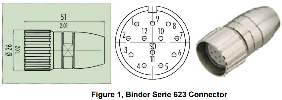 Cable gland nut has to be determined as per cable external diameter and must be separately ordered. It has also to provide the cable shield connection to connector case.
2.2 Binder Serie 423
| GeoSIG | P/N #J_CIR.012.010.M |
| Binder Serie 423 | P/N 99 5629 00 12 |
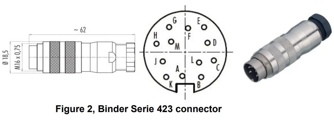 Cable gland nut has to be determined as per cable external diameter and must be separately ordered. It hasalso to provide the cable shield connection to connector case.
2.3 Connector Pin Description
The connector pin assignment and cable colour code can be observed in the table below:
| Binder Connector | SIGNAL | Comment | Colour | ||
| Serie 623 | Serie 423 | ||||
| Pinout | Pinout | ||||
| 1 | A | OUTPUT X (+) | 0 V ± 5 V voltage output, 47 Ω output impedance | White | |
| 2 | B | OUTPUT X (-) | 0 V ± 5 V voltage output inverted, 47 Ω output impedance | Brown | |
| 3 | C | OUTPUT Y (+) | 0 V ± 5 V voltage output, 47 Ω output impedance | Green | |
| 4 | D | OUTPUT Y (-) | 0 V ± 5 V voltage output inverted, 471,1 output impedance | Yellow | |
| 5 | E | OUTPUT Z (+) | 0 V ± 5 V voltage output, 47 Ω output impedance | Grey | |
| 6 | F | OUTPUT Z (-) | 0 V ± 5 V voltage output inverted, 47 Ω output impedance | Pink | |
| 7 | G | TEST INPUT | Test input, output will result in a sensor step response | Blue | |
| 8 | H | GND | Connected to Recorder’s GND | Red | |
| 9 | J | +12 VDC power | Power input, +7 to +15 VDC range, 74.1 mA@ 15 VDC | Black | |
| 10 | K | GROUND | Ground, not connected to mechanical ground | Violet | |
| 11 | L | AUX | Auxiliary input (reserved) | Grey/Pink | |
| 12 | M | GROUND | Ground, not connected to mechanical ground | Red/Blue | |
Table 1. AC-4x Connector Pin Assignment and Cable Colour Code
Mounting
 Small size and single bolt attachment allow the AC-4X to be easily installed saving installation time. Levelling is accomplished via three-point levelling screws.
![]() Do not overtighten the three-point levelling mechanism. This may damage the sensor.
Do not overtighten the three-point levelling mechanism. This may damage the sensor.
The accelerometers must be firmly mounted to a surface and levelled, as the application requires. Check to be sure that the accelerometer is aligned to produce the desired output signals. Acceleration in the direction indicated on the case will produce a positive output signal. The orientation definitions as shipped are:
X = East, Y = North and Z = Vertical (Up).
The accelerometer has single-bolt, 3-feet-levelling mechanism.
The surface should have a scribed north/south orientation line accurately surveyed from reliable markers. The X-axis of the sensor has to be pointed to East or to any other main direction of the structure to monitor. One M8 expanding nut rock anchor must be used for the sensor fixation.
Theory of operation
4.1 Introduction
The AC-43 sensor package is a triaxial accelerometer designed for free field and industrial applications regarding STRONG-MOTION earthquake survey, monitoring and research. This sensor is well suited for applications where a high sensitivity is required.
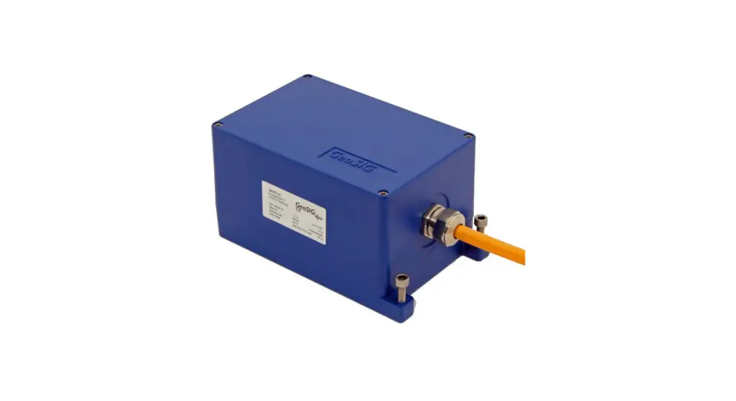
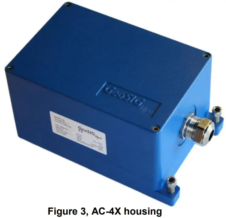
The AC-43 sensor can be optionally installed into a rugged protective housing. This optional protective housing is in stainless steel for optimal environmental resistance. As option, the protective housing could be executed with an IP68 grade for Free field location where the possibility exists of housing submersion.
The sensor could be installed on floor or wall with a modification of the axis organization. With the help of the TEST LINE, the complete sensor can be very easily completely tested. Full scale can be field selected by the user with jumpers.
4.2 Principle
The AC-43 accelerometer is based on the modern MEMS (Micro Electro-Mechanical Systems) technology, consisting of sensing cells assembled in a way that optimizes their performances. This combined with the state of the art proprietary circuit design yields this cost effective and reliable accelerometer.
MEMS cells include linear accelerometer sensing elements which measure the capacitance variation in response to any movement or inclination and a factory trimmed interface chip that converts the capacitance variations into analog or digital signal proportional to the motion.
The DC response allows the sensor to be easily repaired, tilt tested or recalibrated in the field. With the help of the TEST LINE the AC-43 accelerometer can be completely tested assuring proper operation.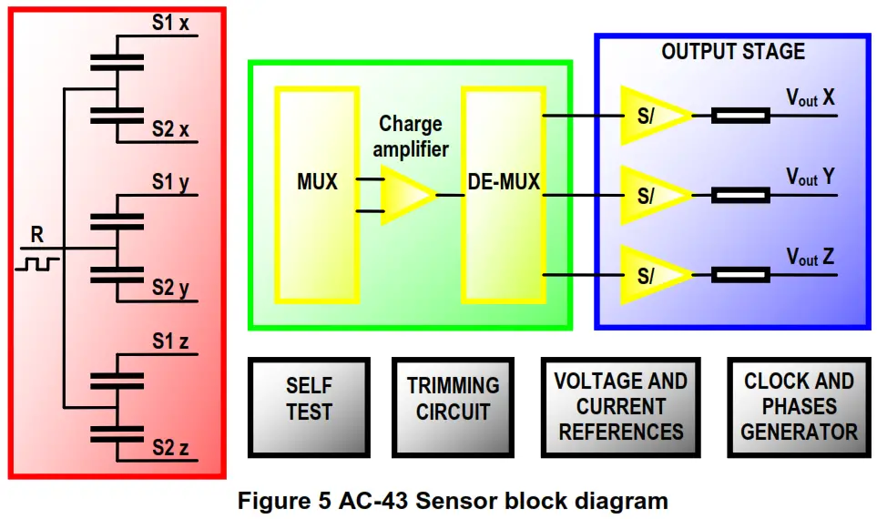 The test signal will move the seismic mass. The movement of the mass generates a voltage across the position detector, which is detected by the differential charge amplifier and induces an output signal.
Electrical configuration
The full scale can be only adjusted by the mean of the gain potentiometer for each axis.
The offset can be at any time readjusted for each channel with a potentiometer without gain re-calibration
Mounting (downhole sensor)
The sensor must be installed in a 3-inch inclinometer tube. At least a 100 mm borehole must be drilled. Depending on the soil condition, it could be required to drill a higher dimension hole and to implement a 120 mm PVC casing to insure a free path when the inclinometer tube is inserted in the borehole.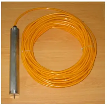
6.1 Borehole preparation
Note: Do not scale the drawing.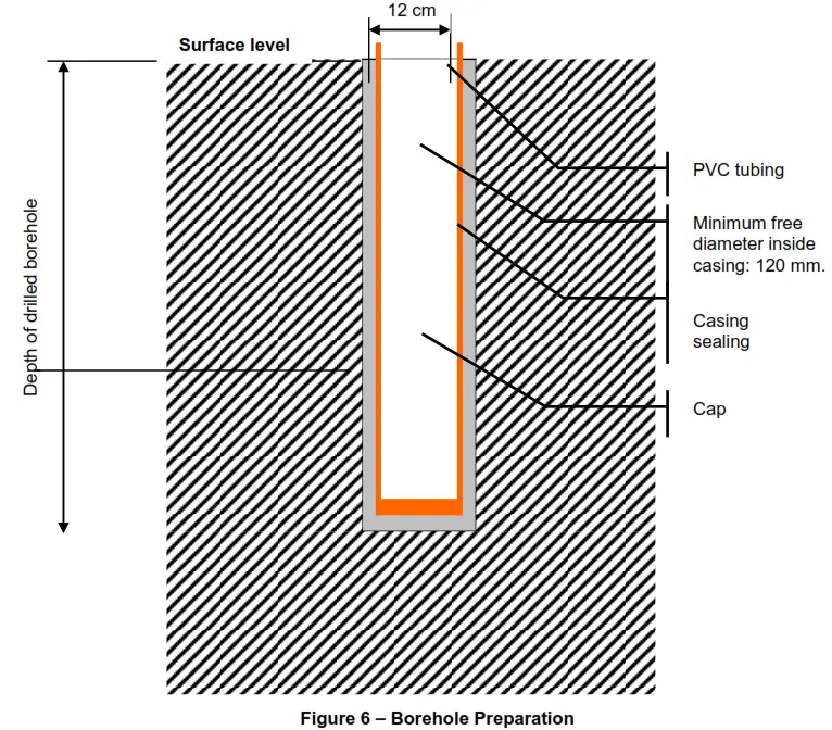 Do not allow concrete mix from casing sealing to enter the casing.
6.2 Inclinometer tube installation
Note: Do not scale the drawing. The number of section is only an example.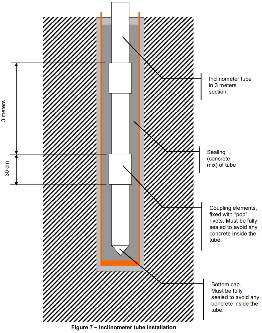
6.3 Sensor installation
Note: Do not scale the drawing. The number of sections is only an example.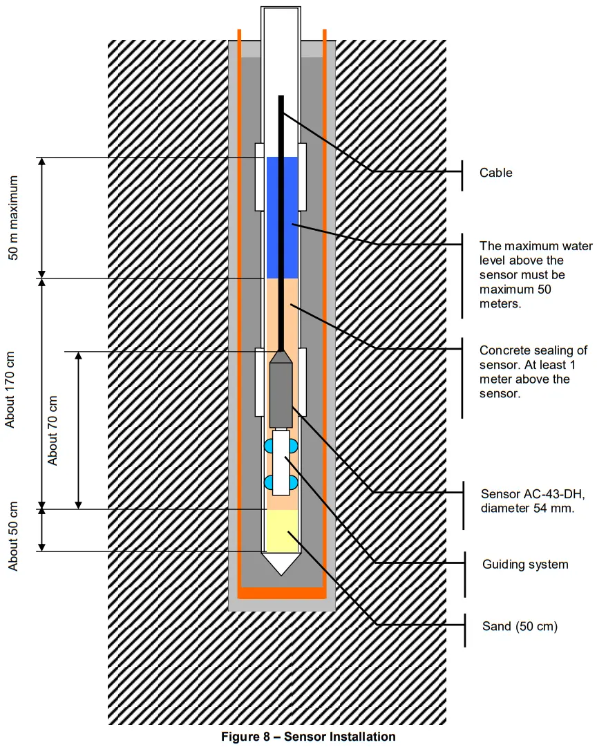
6.4 Inclinometer casing assembly
The borehole must have a casing or the soil must insure that a free path for the inclinometer tube is warranted. It is recommended to insert the inclinometer tube as soon the borehole is ready.
The free path for the inclinometer tube should be 10 to 15 cm, 12 cm typically.
It could be required to insert some water in the casing to sustain the water pressure at the bottom of the borehole.
The inclinometer tube should be mounted with a maximum deviation of ±1° / 3 meters and with a maximum deviation from vertical at sensor location of ±3°. The functional limit for the sensor is ±9°.
The water level in the inclinometer tube should be maximum 50 meters, including fast elevation due to heavy rain.
It is recommended to use the optional assembly kit that GeoSIG can provide (optional) with the inclinometer tube. It will insure a perfect sealing of the tube elements and would avoid concrete mix to enter the tube.
The dimensions of the inclinometer tube are: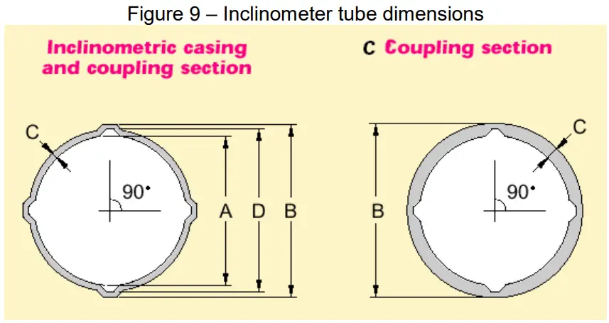
| INCLINOMETRIC CASING (3 m section) | COUPLING ELEMENT | ||||
| A | Inner diameter | 76.1 mm | A | Inner diameter | 81.0 mm |
| B | Groove outer diameter | 86.4 mm | B | Outer diameter | 92.0 mm |
| C | Thickness | 2.2 ±0.1 mm | C | Thickness | 2.2 mm |
| D | Groove inner diameter | 82.0 mm | D | Groove inner diameter | 87.6 mm |
| Length | 3 meters | Length | 300 mm | ||
| Weight | 1.4 Kg/m | Weight | 0.5 kg | ||
| Borehole diameter | > 120 mm | ||||
Table 2 – Inclinometer tube dimensions
The following elements will be inserted in the borehole:
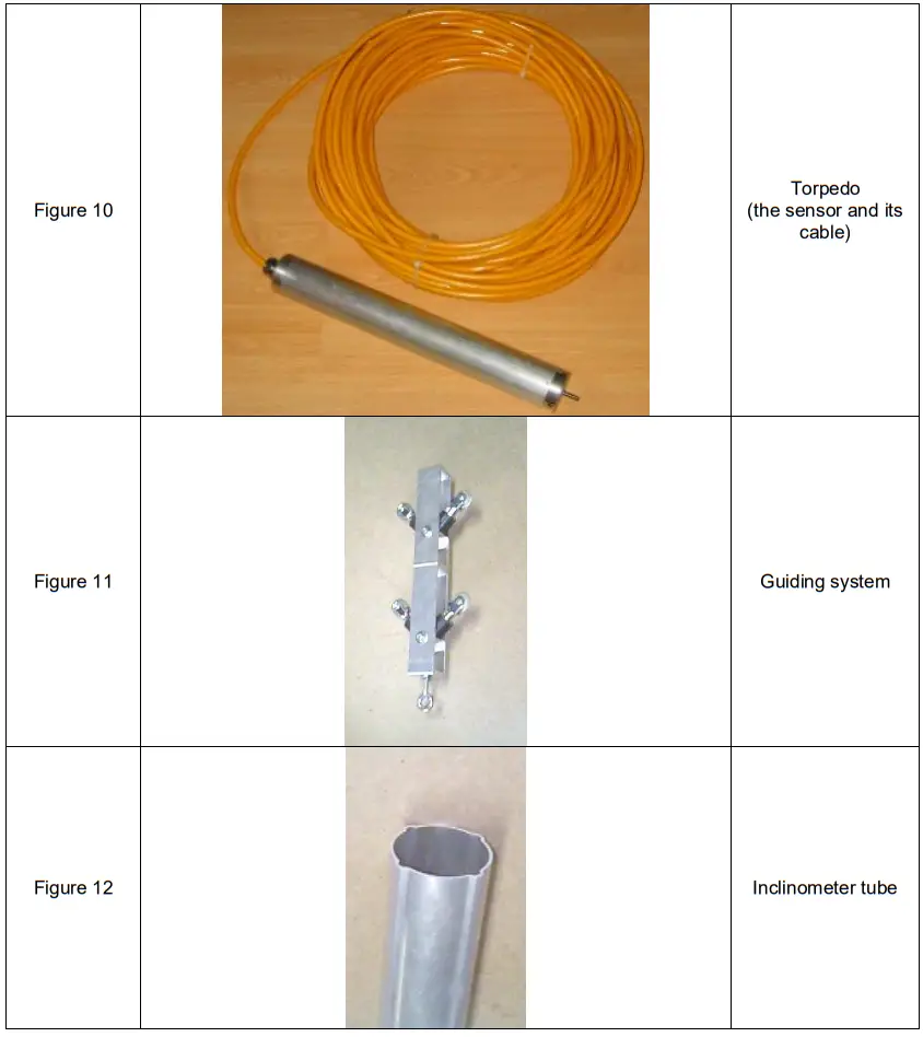
6.5 Axis orientation
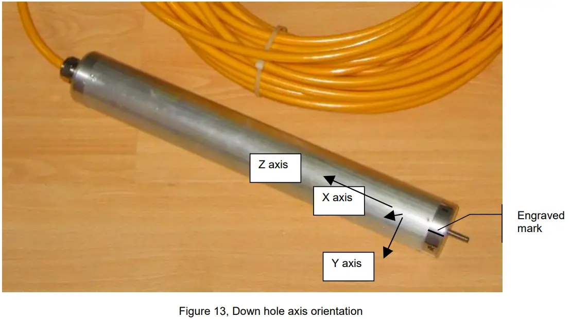
Before the sensor is inserted in the inclinometer tube, the guiding system must be mounted bellow it. The guiding system must be orientated before the insertion.
The engraved mark on bottom cover is showing the positive direction of X axis: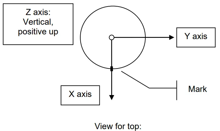
Installation Verification
Please note that temperature compensation device is mounted for each axis inside the sensor and that the temperature in the sensor has to stabilize before accurate measurement can be done. Allow at least half an hour for temperature stabilization.
![]() User Manual
User Manual
AC-43 Accelerometer
11.08.2022/V07


