GeoSIG AC-43 Accelerometer
| Author: | Serge Rudaz |
| Checked: | Talhan Biro |
| Approved: | Johannes Grob |
| Distribution: | GeoSIG Ltd (1), Customer on request |
Document Revision
| Version | Date | Modification | Prepared | Checked | Released |
| 1 | 12.02.2007 | Adapted to new sensor housing; File name and title change | SER | TAB | JOG |
| 2 | 25.02.2008 | Updated with DH version | SER | TAB | JOG |
| 3 | 23.09.2013 | Axis orientation | JLT | MAE | JOG |
| 4 | 06.06.2014 | New logo | VAG | ||
| 5 | 07.05.2019 | Mounting section updated | VAG | ALB | |
| 6 | 24.02.2022 | Housing drawing updated | KEC | ALB | |
| 7 | 04.08.2022 | Updated chapter 2, electrical connector Changed chapter order; updated doc revision table | ALM | ALB | KEC |
| 8 | 21.02.2022 | Removed AC-4X references; Removed downhole option and instructions | KEC | BES | VAG |
| 9 | 03.03.2022 | Updated electrical connector details & photos | KEC | ALB | VAG |
Disclaimer
GeoSIG Ltd reserves the right to change the information contained in this document without notice. While the information contained herein is assumed to be accurate, GeoSIG Ltd assumes no responsibility for any errors or omissions.
Copyright Notice
No part of this document may be reproduced without the prior written consent of GeoSIG Ltd. Software described in this document is furnished under a license and may only be used or copied in accordance with the terms of such a license.
Trademark
All brand names and production names mentioned are trademarks or registered trademarks of their respective holders.
All rights reserved
GeoSIG Ltd Switzerland
Warnings and Safety
 The sensor housing provides no protection against explosive atmosphere. It must not be directly operated in area where explosive gases are present; contact GeoSIG for this kind of special application.
Basic Specifications
| Sensor Series | AC-43 |
| Input range | Acceleration, ±0.625, ±1, ±2, ±3, ±4 or ±5 g |
| Output range | 0 ± 10 Volt differential output |
| Frequency range | From DC to 100 Hz |
| Protections | All connectors pins are protected by Trans Zorb diodes and VDR |
| Power supply | 7 – 15 VDC |
| Current drain | Average 74.1 mA @ 15 VDC |
Electrical Connector
All AC-43 accelerometers are supplied as standard with a 2 m connection cable. Based on the intended use, the 12-pin metallic-style connectors will be supplied in one of the following options: Binder Series 623 or Binder Serie 423.
Binder Serie 623
| GeoSIG | P/N #J_CIR.012.002.F |
| Binder Serie 623 | P/N 99 4606 00 12 |
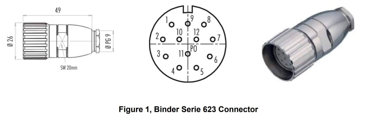
The cable gland nut is determined according to cable external diameter, and it must be ordered separately. The cable gland nut must also provide the cable shield connection to the connector case.
Binder Serie 423
| GeoSIG | P/N #J_CIR.012.010.M |
| Binder Serie 423 | P/N 99 5629 00 12 |
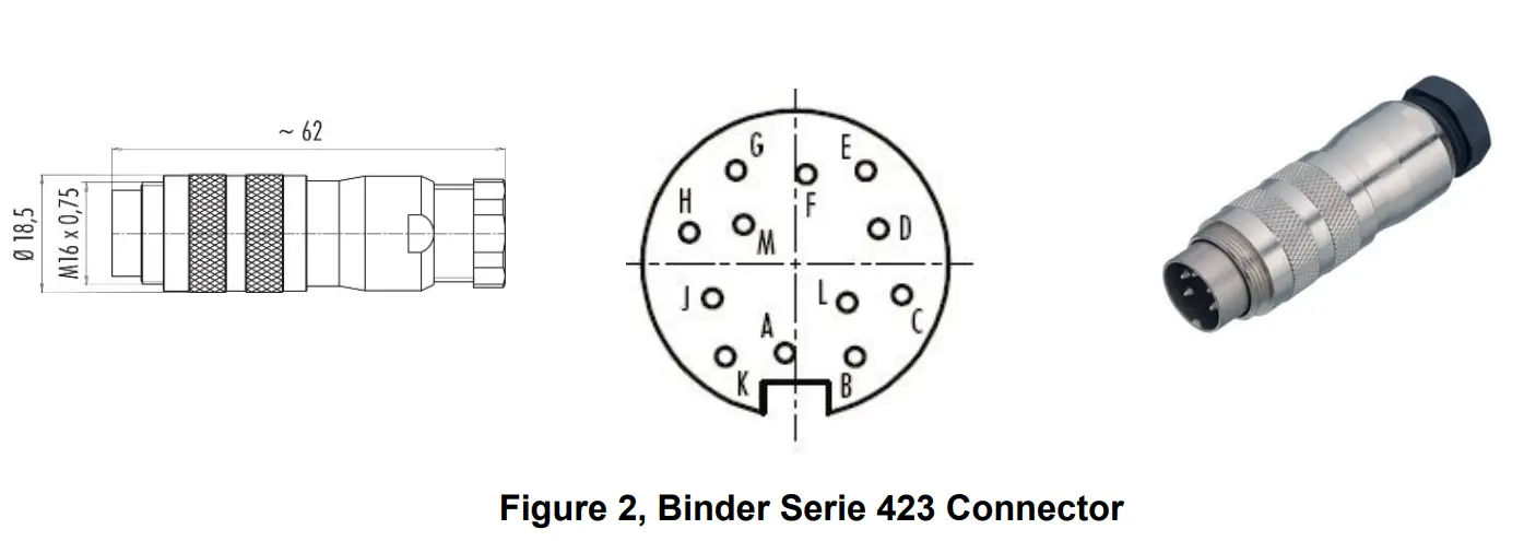
The cable gland nut is determined according to cable external diameter, and it must be ordered separately. The cable gland nut must also provide the cable shield connection to the connector case.
Connector Pin Description
The connector pin assignment and cable colour code can be observed in the table below:
| Binder Connector | SIGNAL | Comment | Colour | ||
| Serie 623 | Serie 423 | ||||
| Pinout | Pinout | ||||
| 1 | A | OUTPUT X (+) | 0 V ± 5 V voltage output, 47 W output impedance | White | |
| 2 | B | OUTPUT X (-) | 0 V ± 5 V voltage output inverted, 47 W output impedance | Brown |  |
| 3 | C | OUTPUT Y (+) | 0 V ± 5 V voltage output, 47 W output impedance | Green |  |
| 4 | D | OUTPUT Y (-) | 0 V ± 5 V voltage output inverted, 47 W output impedance | Yellow |  |
| 5 | E | OUTPUT Z (+) | 0 V ± 5 V voltage output, 47 W output impedance | Grey |  |
| 6 | F | OUTPUT Z (-) | 0 V ± 5 V voltage output inverted, 47 W output impedance | Pink |  |
| 7 | G | TEST INPUT | Test input, output will result in a sensor step response | Blue |  |
| 8 | H | GND | Connected to Recorder’s GND | Red |  |
| 9 | J | +12 VDC power | Power input, +7 to +15 VDC range, 74.1 mA @ 15 VDC | Black |  |
| 10 | K | GROUND | Ground, not connected to mechanical ground | Violet |  |
| 11 | L | AUX | Auxiliary input (reserved) | Grey/Pink |  |
| 12 | M | GROUND | Ground, not connected to mechanical ground | Red/Blue | |
Table 1. AC-43 Connector Pin Assignment and Cable Colour Code
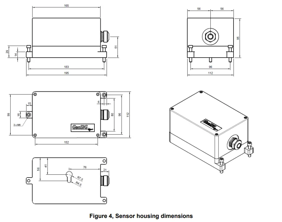
Mounting
Small size and single bolt attachment allow the AC-43 to be easily installed, saving installation time. Levelling is accomplished via three-point levelling screws.
![]() Do not overtighten the three-point levelling mechanism. This may damage the sensor.
Do not overtighten the three-point levelling mechanism. This may damage the sensor.
The accelerometers must be firmly mounted to a surface and levelled, as the application requires. Check to ensure that the accelerometer is aligned to produce the desired output signals. Acceleration in the direction indicated on the case will produce a positive output signal. The orientation definitions as shipped are:
X = East,
Y = North, and Z = Vertical (Up).
The accelerometer has single-bolt, 3-feet-levelling mechanism.
The surface should have a scribed north/south orientation line accurately surveyed from reliable markers. The X-axis of the sensor has to be pointed to East or to any other main direction of the structure to monitor. One M8 expanding nut rock anchor must be used for the sensor fixation.
Theory of Operation
Introduction
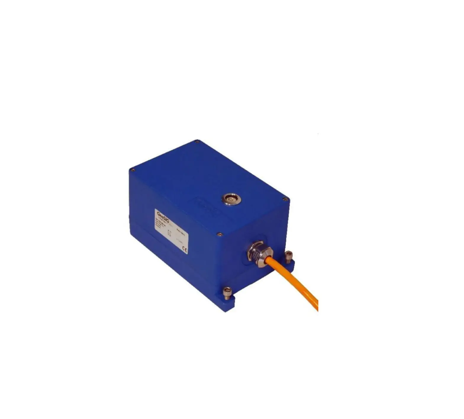
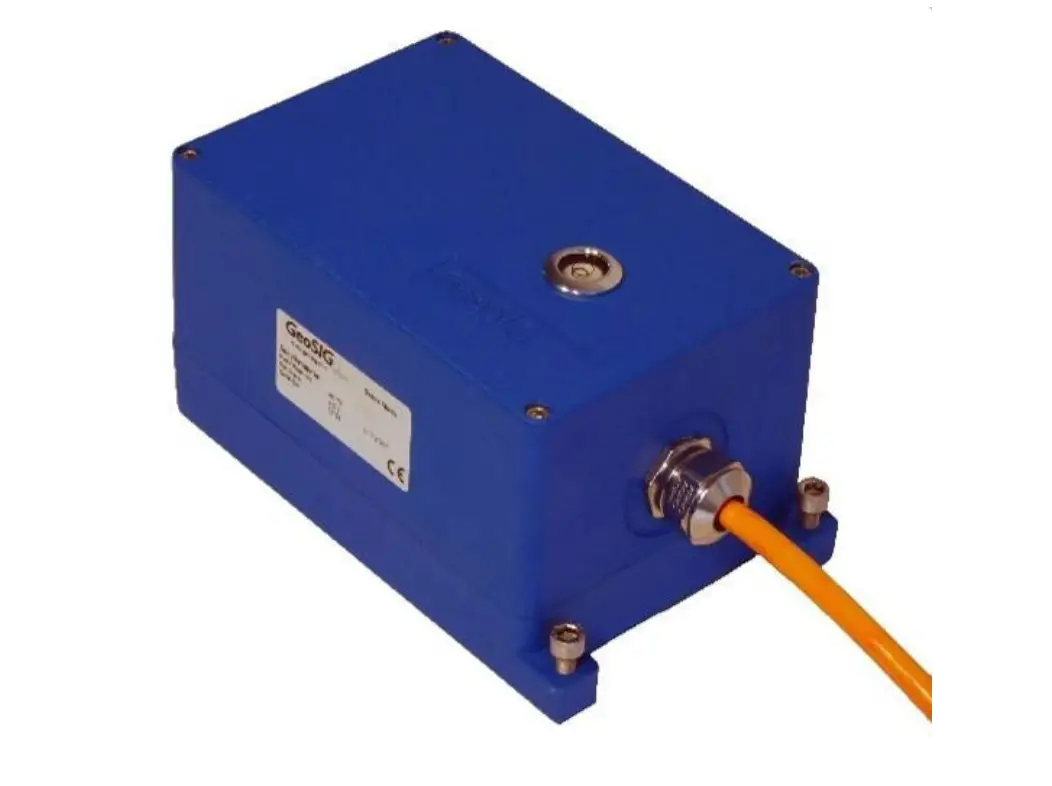
The AC-43 sensor package is a triaxial accelerometer designed for free field and industrial applications regarding STRONG-MOTION earthquake survey, monitoring and research. This sensor is well suited for applications where a high sensitivity is required.
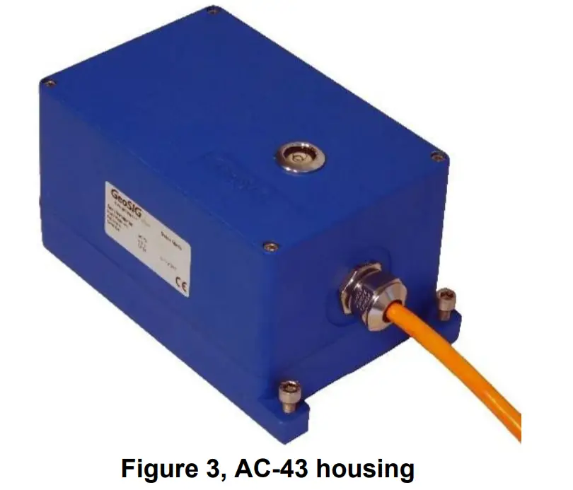
The AC-43 sensor can be optionally installed into a rugged protective housing of stainless steel for optimal environmental resistance. Optionally, the protective housing could be executed with an IP68 grade in circumstances where it is possible that the housing might become submerged in the free field location.
The sensor could be installed on either floor / ceiling or on the wall with a modification of the axis configuration. With the help of the TEST LINE, the complete sensor can be very easily and fully tested. Full scale can be field selected by the user with jumpers.
Principle
The AC-43 accelerometer is based on the modern MEMS (Micro Electro-Mechanical Systems) technology, consisting of sensing cells assembled in a way that optimises their performances. This, combined with the state-of-the-art proprietary circuit design, yields this cost effective and reliable accelerometer. MEMS cells include linear accelerometer sensing elements, which measure the capacitance variation in response to any movement or inclination, and a factory-trimmed interface chip that converts the capacitance variations into analog or digital signal proportional to the motion.
The DC response allows the sensor to be easily repaired, tilt tested or recalibrated. With the help of the TEST LINE, the AC-43 accelerometer can be completely tested, assuring proper operation.
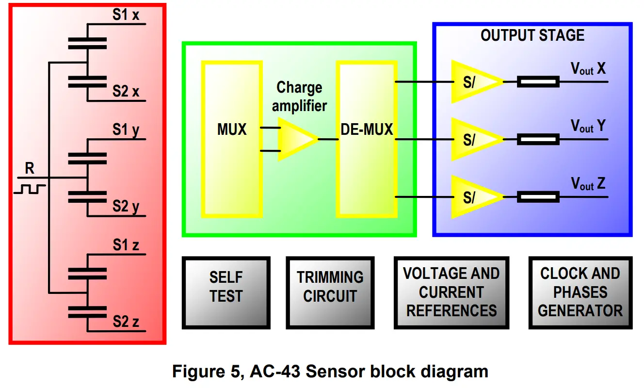
The test signal will move the seismic mass. The movement of the mass generates a voltage across the position detector, which is detected by the differential charge amplifier and induces an output signal.
CUSTOMER SUPPORT
GeoSIG Ltd, Wiesenstrasse 39, 8952 Schlieren, Switzerland
Phone: + 41 44 810 2150, Fax: + 41 44 810 2350
[email protected], www.geosig.com