![]()
![]()
Wiser Electrical Heat Switch![]()
Wiser Electrical Heat Switch
![]()
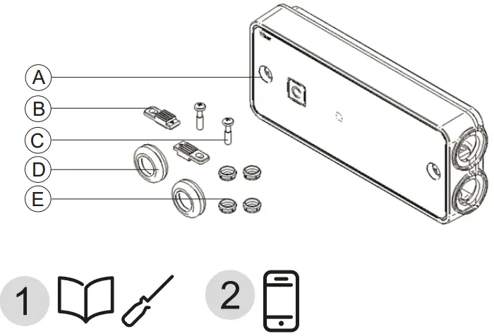
Fig. 1 – Install position
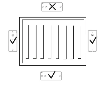
Fig. 2 – Mounting surface preparation
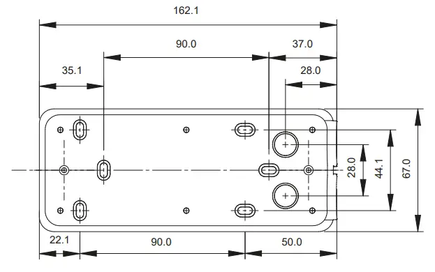
Fig. 3 – Pierce rubber grommet
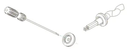

Fig. 4 – Insert cables
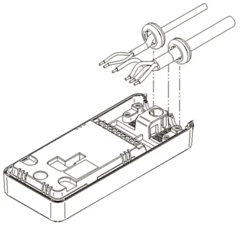
Fig. 5 – Secure cables
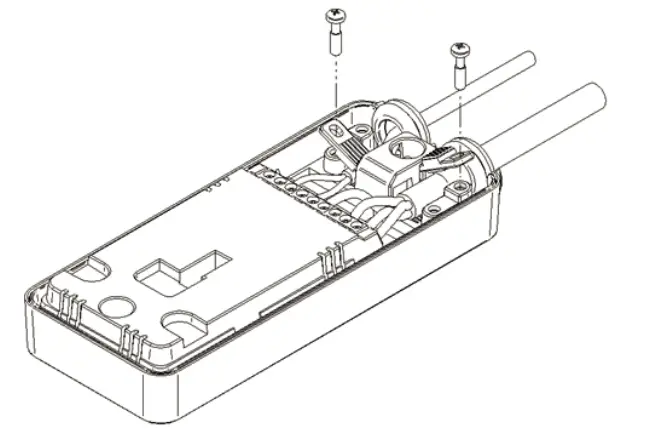
Fig. 6 – Blanking plugs
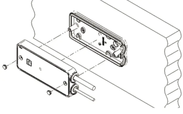
Fig. 7 – In-Out Configuration
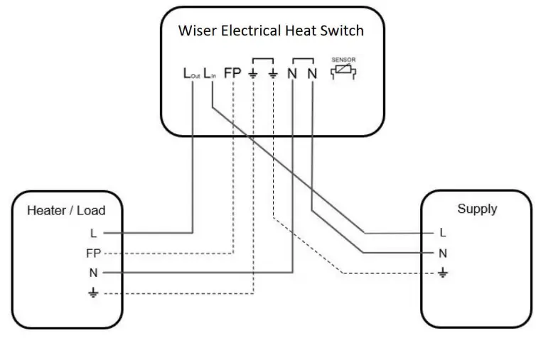
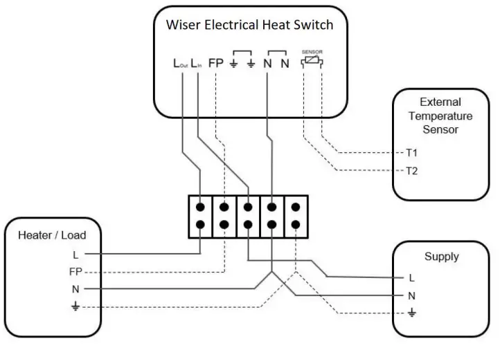
Fig. 8 – Wiring centre configuration
In the box
A Wiser Electrical Heat Switch
B 2x Cable Clamps
C 2x Cable Clamps Screws
D 2x Rubber Grommets
E 4x Blanking Plugs
Warnings
IMPORTANT – Do not attempt to install this product if you are not familiar with how to install mains powered electrical appliances. IMPORTANT – Not SELV – Fixed wiring only, to comply with current local regulations.
CAUTION – Before installation, make sure the mains supply is switched off.
NOTE – When inserting the conductors into the connector blocks make sure they are securely screwed down.
Installation
- The Electrical Heat Switch must be installed below or to the side of any heat source. — Fig. 1
- Prepare mounting surface as per the diagram.
NOTE: Breakout tabs can be removed to provide 4x extra mounting holes and 2x larger holes for rear cover cable entry. — Fig. 2 - Securely attach the black rear cover to the mounting surface.
- Prepare cable for wiring. Insulation should be stripped back 6.5mm.
Note: for installations with loads of 16A a minimum of 1.5mm2 conductor should be used. - Pierce the rubber grommets with a small screwdriver and thread through the cable. To ensure IP44 ingress protection a tight seal must exist between the rubber grommets and the cable sheath. —Fig. 3
- Push down the cables into the front cover receptacles as shown in the image below. — Fig. 4
- Make the wiring connections, as shown in the wiring diagrams Figs. 7 & 8, for the appropriate system. For surface wiring ensure rubber grommets are fitted to cable before wiring into connector blocks. For In-wall wiring remove the rear cover break out tabs and feed cables through prior to wiring into connector blocks.
- Secure the cable with the cable clamps and screws provided in your fixing kit. Note: cable clamps can be placed in high or low receptacles and can also be flipped to better compress the chosen cable. — Fig. 5
- Position Front Cover over Rear Cover mounted on wall, push together and ensure Rubber Grommets sit neatly in their receptacles.
- Fix together via two screws located on the front surface — both steps are shown in Fig. 6
- To finish off pop the two blanking plug components over the screw heads. — Fig. 6
Pairing Wiser Electrical Heat Switch
Standalone Operation — Before pairing the Wiser Electrical Heat Switch, basic manual control can be performed by pressing the button. A press of the button toggles the output on and off. The LED lights amber to show output is on.
Joining – When joining the Wiser Electrical Heat Switch to a Wiser system, please download the app and follow the instructions to join the device.
To initiate joining on the Wiser Electrical Heat Switch press the button for more than 2 seconds, the LED will start alternating between amber and green to confirm joining is in progress.
The LED will then flash green for 5 seconds on success, or red for 5 seconds if failed to join.
Factory reset – To return the Wiser Electrical Heat Switch to factory settings. Press and hold the button for more than 20 seconds. After 15 seconds the LED will flash red. Once the LED stops flashing red, release the button and the unit is factory reset.
Product information is available
For more detailed product information is available on the Internet -> Download document
 http://wiser.draytoncontrols.co.uk/
Technical data
| Product name | Wiser Electrical Heat Switch |
| Product reference | WE714U1 A0902 |
| Rated voltage | 230V —50Hz AC ONLY |
| Power consumption | 7.3 W |
| Purpose of control | Electrical Cotrol, Manual + Automatic Control, Sensing Control |
| Type of load and rated current | 16A Resistive or (3A) Inductive Load Circuit for pilot load. (FP) |
| Ingress Protection | IP44* 1P44 Ingress protection achieved in laboratory testing. Final IP rating dependent on installation. For best results ensure a good seal exist between the rubber grommets, cable and enclosure. |
| Terminals and Wiring | Suitable for conductor sizes 1.0-2.5mmz Insuation strip lengt 6.5mm |
| Operating Temperature | 0 to 60°C |
| Storage Temperature | -20°C to 65°C |
| Class of control | Class II |
| Method of mounting control | Independently mounted control |
| Method of providing earthing control | The control is not earthed Terminals are provided for linking external earthing conductors |
| Method of attachment for nondetachable cords | Type Y attachments |
| Extent of sensing element (if installed) | External temperature sensor setpoint range of 5°C to 30°C +-5% |
| Operating value | User variable time control of electrical/heating system (only at system level through HubR) |
| Pollution degree | 2 |
| Rated impulse voltage | 4kV |
| Ball pressure test | 115°C |
| Software class | A |
| Radio Technology/ Frequency | 2.4GHz |
| Radio signal range | 30m free space |
| Maximum radio frequency power transimmted | +13dBm (20mW) |
| Relevant directives | Radio Equipment Directives (RED) 2014/53/EU, RoHS directive 2011/65/EU and 2015/863/EU |
| Applied standards | EN60730-1; EN60730-2-9; EN 300 328; EN 301 489-1 |
Dispose of the device separately from household waste at an official collection point. Professional recycling protects people and the environment against potential negative effects.
Trademark
- Apple® and App Store® are brand names or registered trademarks of Apple Inc.
- Google PlayTM Store and Android.” are brand names or registered trademarks of Google Inc. Other brands and registered trademarks are properties of their relevant owners.
Declaration of conformity
Hereby, Schneider Electric Controls UK, declares that this product is in compliance with the essential requirements and other relevant provisions of RADIO EQUIPMENT DIRECTIVE 2014/53/EU. Declaration of conformity can be downloaded on: www.draytoncontrols.co.uk
If you have technical questions, please contact the Customer Care Centre in your country.
![]() Schneider Electrical Controls Ltd
Schneider Electrical Controls Ltd
401 Southway Drive
Plymouth PL6 6QT
Schneider Electric Industries SAS
35 rue Joseph Monier
F – 92500 Rueil-Malmaison
Technical Helpline: 0333 6000 622
[email protected]
www.wiser.draytoncontrols.co.uk
schneider-electric.com/contact
schneider-electric.com/wiser-support
06490 001 I B


