Winseon RTGA71 Thermopile Gas Sensor
Statement
This manual copyright belongs to Zhengzhou Winsen Electronics Technology Co., LTD. Without written permission, any part of this manual shall not be copied, translated, or stored in a database or retrieval system, also can’t spread through electronic, copying, or record ways. Thanks for purchasing our product. In order to let customers use it better and reduce the faults caused by misuse, please read the manual carefully and operate it correctly in accordance with the instructions. If users disobey the terms or remove, disassemble, or change the components inside of the sensor, we shall not be responsible for the loss. The specific such as color, appearance, sizes &, etc, please in kind prevail. We are devoting ourselves to product development and technical innovation, so we reserve the right to improve the products without notice. Please confirm it is the valid version before using this manual. At the same time, users’ comments on the optimized using way are welcome. Please keep the manual properly, in order to get help if you have questions during the usage in the future.
RTGA71 Thermopile Gas Sensor
Production Description
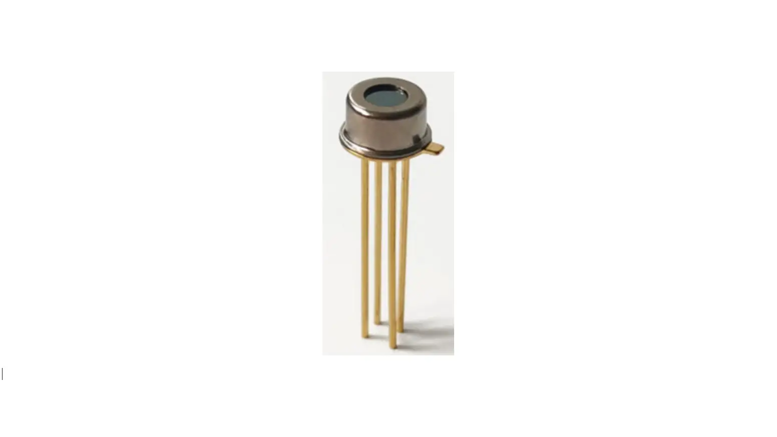
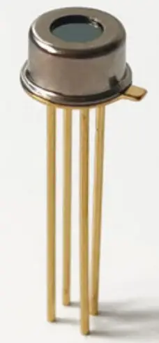
RTGA71 sensor is a single-channel thermopile gas sensor, which contains a thermopile chip based on MEMS technology and connects hundreds of pairs of thermocouples in series, to convert the absorbed infrared radiation into a voltage signal. There is a narrow-band filter in the front of the sensor, and the sensor can be used for the detection of carbon dioxide concentration. The sensor NTC itself has temperature compensation, to improve the measurement accuracy. 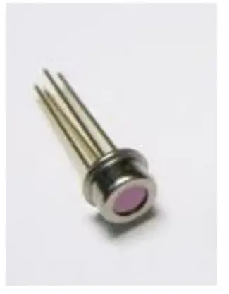
Features
- TO-46 metal package
- High sensitivity
- Quick response, Good stability
- High transmittance of narrowband filter
- High precision NTC
Applications
- NDIR (CO2) Gas Detection equipment
- Indoor air quality detection and HVAC system control
- CO2 gas control in industrial workshop
- CO2 emission control of combustion furnace
- Human breath detection
- Interior air quality monitoring of automotive
Table 2 RTGA71 thermopile parameters
| Parameter | Value | Unit | Remarks |
| Chip size | 1.35×1.35 | mm | / |
| Field of view | 95 | Degree | Above 50% |
| Filter center wavelength | 4.26 | um | |
| Thermopile resistor | 76±10 | KΩ | 25℃,1V |
| Noise voltage | 38 | nV/Hz1/2 | 25℃ |
| Noise equivalent power | 0.23 | nW/Hz1/2 | 500K, 1Hz, 25℃ |
| Response rate | 160±40 | V/W | 500K, 1Hz, 25℃ |
| Temperature coefficient of resistance | 0.06 | %/℃ | 25℃~75℃ |
| Time constant | ≤13 | ms | |
| Chip Detection rate | 1.5 ×10⁸ | cmHz1/2/W | 500K, 1Hz, 25℃ |
| NTC resistance | 100 ± 1% | KΩ | 25℃ |
| NTC(β) | 3950 ± 1% | / | 25℃/50℃ |
| Working temperature | -30 ~ 125℃ |
Sensor Diagram(unit:mm)
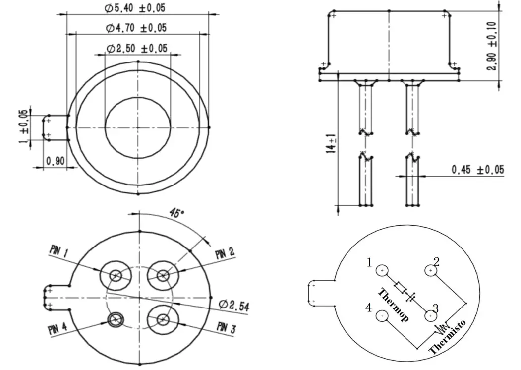
| Pin | 1 | 2 | 3 | 4 |
| Definition | Thermopile positive | NTC | Thermopile negative | GND |
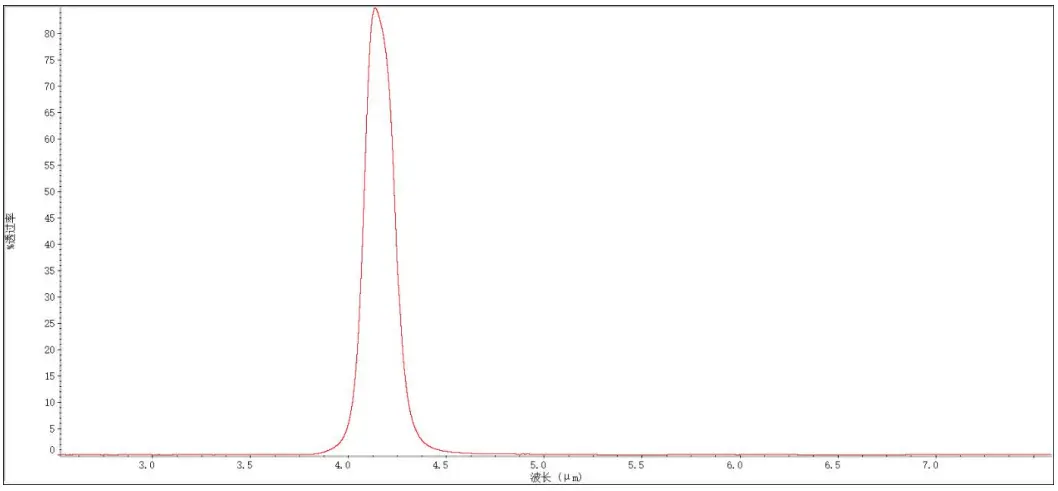
Filter Performance Curve
- Filter performance curve:
center wavelength 4.26μm; peak wavelength transmittance is greater than 80%, and half-width is 180nm
- Thermistor (NTC) R-T Table
T(℃) R(KΩ) T(℃) R(KΩ) T(℃) R(KΩ) T(℃) R(KΩ) T(℃) R(KΩ) –40 3179.00 –6 439.56 28 87.80 62 22.66 96 6.97 –39 2980.73 –5 417.22 29 84.11 63 21.83 97 6.75 –38 2796.06 –4 396.14 30 80.59 64 21.05 98 6.53 –37 2623.95 –3 376.25 31 77.24 65 20.29 99 6.33 –36 2463.46 –2 357.47 32 74.04 66 19.56 100 6.13 –35 2313.73 –1 339.73 33 70.99 67 18.86 101 5.94 –34 2173.97 0 322.98 34 68.07 68 18.19 102 5.75 –33 2043.44 1 307.14 35 65.29 69 17.54 103 5.58 –32 1921.48 2 292.17 36 62.64 70 16.92 104 5.40 –31 1807.49 3 278.02 37 60.11 71 16.33 105 5.24 –30 1700.89 4 264.63 38 57.68 72 15.76 106 5.08 –29 1601.17 5 251.96 39 55.37 73 15.21 107 4.92 –28 1507.85 6 239.96 40 53.16 74 14.68 108 4.77 –27 1420.48 7 228.61 41 51.05 75 14.17 109 4.63 –26 1338.66 8 217.85 42 49.03 76 13.68 110 4.49 –25 1262.00 9 207.66 43 47.10 77 13.21 111 4.36 –24 1190.15 10 198.00 44 45.25 78 12.76 112 4.23 –23 1122.79 11 188.84 45 43.49 79 12.32 113 4.10 –22 1059.61 12 180.16 46 41.79 80 11.90 114 3.98 –21 1000.34 13 171.92 47 40.18 81 11.50 115 3.86 –20 944.72 14 164.10 48 38.63 82 11.11 116 3.75 –19 892.50 15 156.68 49 37.15 83 10.74 117 3.64 –18 843.46 16 149.63 50 35.88 84 10.38 118 3.54 –17 797.38 17 142.94 51 34.37 85 10.03 119 3.43 –16 754.09 18 136.58 52 33.06 86 9.70 120 3.34 –15 713.38 19 130.54 53 31.81 87 9.38 121 3.24 –14 675.11 20 124.79 54 30.62 88 9.07 122 3.15 –13 639.10 21 119.33 55 29.47 89 8.77 123 3.06 –12 605.22 22 114.13 56 28.37 90 8.48 124 2.97 –11 573.33 23 109.19 57 27.32 91 8.21 125 2.89 –10 543.30 24 104.48 58 26.31 92 7.94 –9 515.01 25 100.00 59 25.34 93 7.69 –8 488.36 26 95.73 60 24.41 94 7.44 –7 463.24 27 91.67 61 23.51 95 7.20
Note:
- The sensor must first calibrate the resistance of the thermistor NTC;
- The sensor test is affected by factors such as black body temperature, distance, and environment. The V-T table is for reference only. The V-T meter needs to be calibrated before use.
- The output voltage of the sensor is easily affected by the NTC resistance value. It is necessary to increase the thermal resistance and heat capacity to increase temperature stability. Generally, metal (copper, aluminum) kits are used;
- In order to reduce the thermal interference between the sensor pins, the sensor pins should be thermally isolated when making a PCB;
- The hand soldering temperature should be 330±20℃, and single pin soldering time should not exceed 3s;
- Frequent, excessive vibration, strong impact or collision will cause a resonance inside the sensor to break.
Address:
Zhengzhou Winsen Electronics Technology Co., Ltd Add: No.299, Jinsuo Road, National Hi-Tech Zone, Zhengzhou 450001 China
Tel: +86-371-67169097/67169670
Fax: +86-371-60932988
E-mail: [email protected]
Website: www.winsen-sensor.com


