JXCT RS485 ModbusJXBS-3001-NPK-RS Soil NPK Sensor
INTRODUCTION
Product Overview
The NPK sensor is designed for detecting the content of nitrogen, phosphorus and potassium in soil, determining the fertility of the soil and facilitating the evaluation of the soil condition by the customer system.
The product can be widely used in rice fields, greenhouse cultivation, rice, vegetable cultivation, orchard nursery, flowers and soil research.
| Parameters | ||
| Parameters | Technical Specs | |
| Measure Range | 0-1999mg/kg | |
| Accuracy | ±2%F.s | |
| Resolution | 1mg/kg(mg/l) | |
| Response Time (T90, Seconds) | <10s | |
| Working Temperature | 5-45℃ | |
| Working Humidity | 5-95%RH (Relative humidity), no condensation | |
| Baud Rate | 2400/4800/9600 | |
| Communication Port | RS485 | |
| Power Supply | 12V-24V DC | |
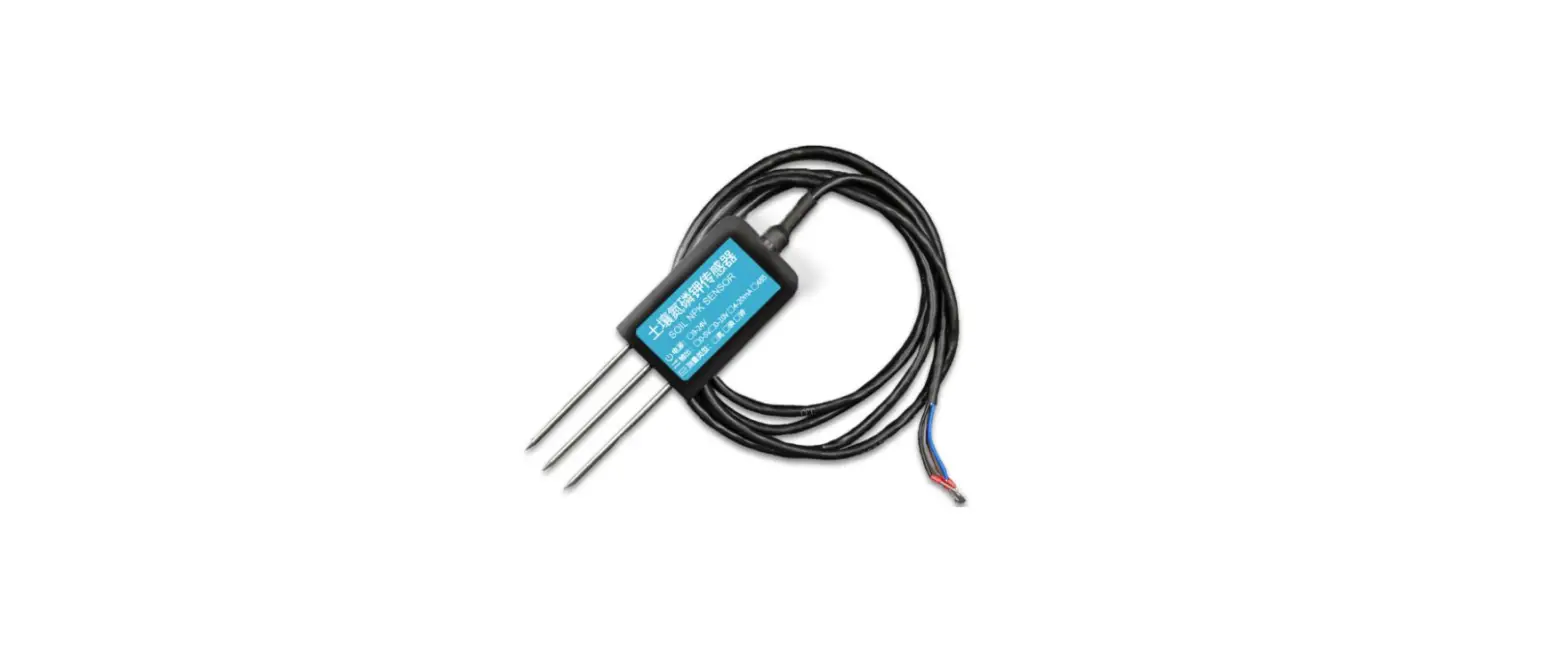
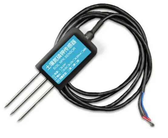
| 1.3 Structure & Size The sensors probes are made | of | 316 stainless steel for anti-rust and electrolysis |
Structure & Size
The sensors probes are made of 316 stainless steel for anti-rust and electrolysis resistance, salt and alkali corrosion resistance purpose, to ensure the long-term operation of the probe part. Sensor body is made IP68, filled with high-density epoxy resin for high-temperature vacuum filling, effectively preventing moisture from. Rs485 Cable length is 0.6m by default. Can be customized.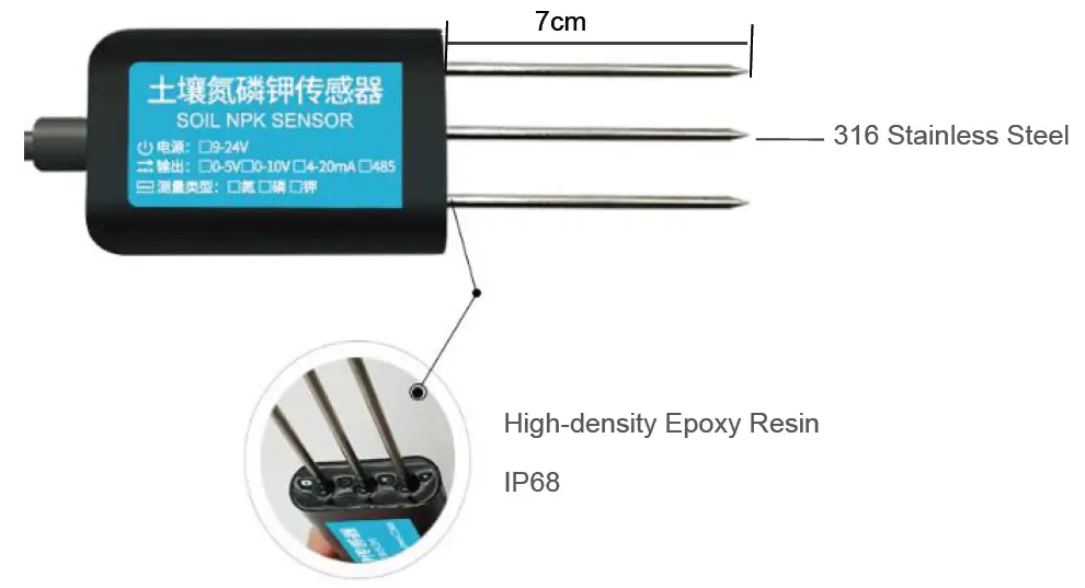
System Frame Diagram
The device can be connected directly to the PLC with 485 interface, and it can be connected to the MCU through the 485 interface chip. The microcontroller and PLC can be programmed to match the sensor by the modbus protocol specified later. User can also connect the sensor to the computer by using USB to 485 converter, and use the sensor configuration tool provided by JXCT for configuration and testing.
Picture 1: Single Sensor Working Diagram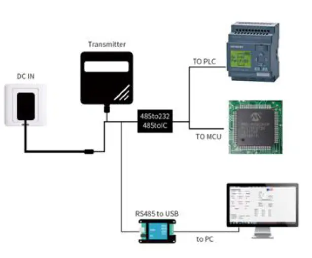
This product can also be used in combination with multiple sensors on one 485 bus. Please observe the “485 Bus Field Wiring Code” when performing 485 bus combination (see Appendix). In theory, one bus can connect more than 16 485.sensors. If you need to connect more 485 sensors, you can use 485 repeater to expand more 485 devices, and the other end to connect PLC with 485 interface and pass 485 interface chip. Connect to the micro-controller, or use USB to 485 to connect to the computer, use the sensor configuration tool provided by our company for configuration and testing.
Picture 2: Multiple Sensors Working Diagram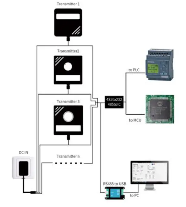
Hardware Connections
Product & Accessories
Check the list of devices before installation:
Interface Description
The power interface can be 12-24V for wide voltage power supply. When wiring the 485 signal line, note that the A/B lines cannot be connected in reverse, and the addresses between multiple devices on the bus cannot conflict.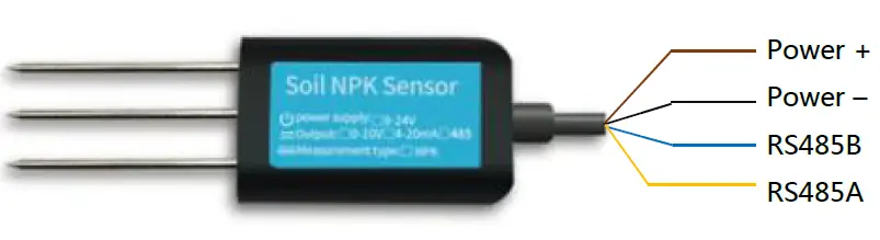
Note: Please be careful not to connect the wrong line sequence. The wrong wiring will cause the device to burn out. The factory default supply of 1.5 meters long wire, customers can extend the wire as needed or in sequence. Note that there is no yellow line in the line sequence that may be provided in some factory batches, in which case the gray line is equivalently replaced by the yellow line.
Surface Measurement Method
Select the appropriate measurement location, avoid the stone, ensure that the steel needle will not touch the hard object, throw off the topsoil according to the required measurement depth, keep the original soil tightness under the ground, hold the sensor vertically into the soil, insert It is not allowed to sway from side to side. It is recommended to measure the average for multiple measurements within a small range of one measurement point.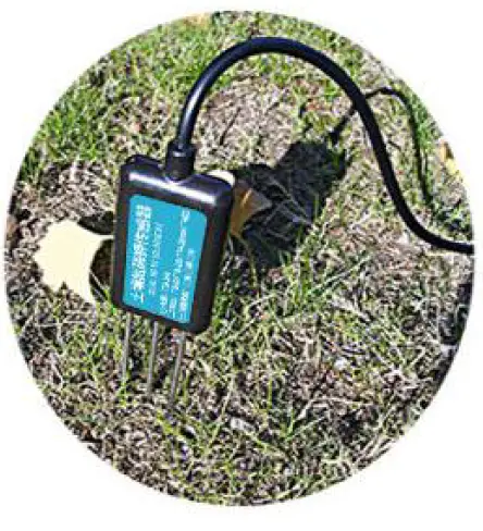
Buried Measurement Method
Vertically dig pits with a diameter of >20cm, insert the sensor steel needle horizontally into the pit wall at a given depth, fill the pits tightly, and stabilize for a period of time, then measure and record for several days, months or even longer.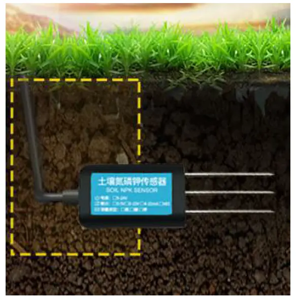
Remarks
- The steel needle must be inserted into the soil during the measurement.
- Avoid strong sunlight directly on the sensor for high temperature. Use in the field to prevent lightning strikes.
- Do not violently bend the steel needle, do not pull the sensor lead wire, do not beat or violently hit the sensor.
- The sensor protection class IP68 can soak the sensor in the water.
- Due to the presence of radio frequency electromagnetic radiation in the air, it is not suitable to be energized in the air for a long time.
Configuration Tool Installation
JXCT provides the matching “SENSOR MONITORING SOFTWARE”, which can conveniently use the computer to read the parameters of the sensor, and flexibly modify the device ID and address of the sensor.
Sensor access to the computer
fter the sensor is properly connected to the computer via USB to 485 and powered, find COM port in the computer (“My Computer – Properties – Device Manager – Port” to view the COM port). Shown as in below screenshot: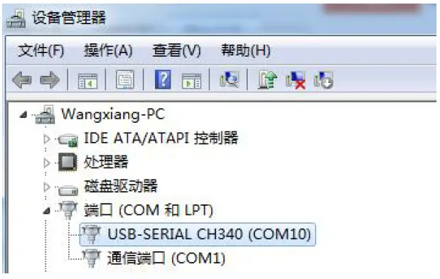
As shown in above, serial port number is COM10 at this time. Please remember this serial port. It shall be filled in the serial port number in the sensor monitoring software. If the COM port is not found in the device manager, it means that you have not plugged in the USB to 485 or did not install the driver correctly, please contact the technical staff for assistance.
Use of sensor monitoring software
The configuration interface is as shown in the figure. First, obtain the serial port number according to the method in section 3.1 and select the correct serial port, then click to automatically obtain the current baud rate and address to automatically detect all devices and baud rates on the current 485 bus. . Please note that there is only one sensor on the 485 bus that needs to be automatically acquired using the software.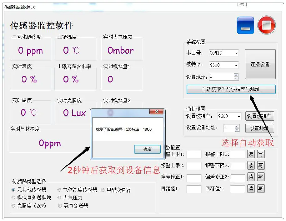
Then click on the connected device to get sensor data information in real time. If your device is a gas concentration sensor, please select “Gas Concentration Sensor” at the sensor type, “Formaldehyde Transmitter” for the formaldehyde sensor, “Analog Transmitter Module” for the analog transmitter, and “Atmospheric Pressure” for the atmospheric pressure sensor. “Sensor”, the illuminance sensor selects “Optical Light 20W”, the oxygen sensor selects “Oxygen Transmitter”, and the other sensors select the default “No Other Sensor”.
Modify the baud rate and device ID
In the case of disconnecting the device, click the device baud rate and setting address in the communication settings to complete the relevant settings. Please note that after the setting, please restart the device, and then “automatically obtain the current baud rate and address”, you can find the address. And the baud rate has been changed to the address and baud rate you need. If you need to modify the baud rate and address using the modbus command, you can refer to the appendix “How to Modify the Baud Rate and Address Using the modbus Command”.
Communication Protocol
Communication Basic Parameters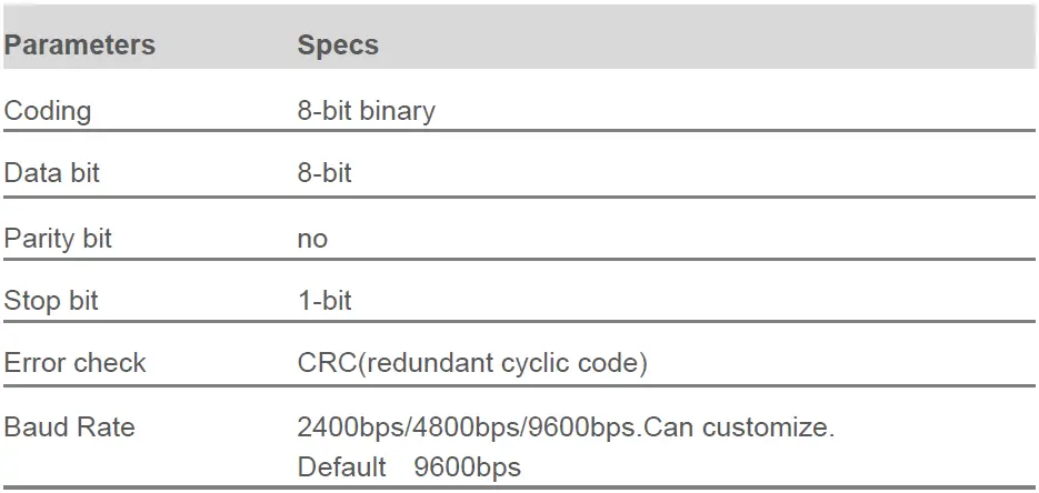
Data Frame Format Definition
Adopt Modbus-RTU communication protocol, the format is as follows:
- Initial structure ≥ 4 bytes of time
- Address code = 1 byte
- Function code = 1 byte
- Data area = N bytes
- Error check = 16-bit CRC code
- End structure ≥ 4 bytes of time
- Address code: is the address of the transmitter, which is unique in the communication network (factory default 0x01).
- Function code: The instruction function of the command sent by the host. This transmitter only uses function code 0x03 (read register data).
- Data area: The data area is the specific communication data. Note that the 16-bit data high byte is in front!
- CRC code: Two-byte check code.
Inquiry Frame
| Address Code | Function Code | Register Start Address | Register Length | CRC_L | CRC_H |
| 1bit | 1bit | 2bit | 2bit | 1bit | 1bit |
Answer Frames
| Address code | Function Code | Effective number of bytes | Data area | Second data area | Nth data area | Check code |
| 1bit | 1bit | 2bit | 2bit | 1bit | 2bit | 2bit |
Register Address
| Register | PLC or configuration | Content | Operating |
| Address | address | ||
| 001E H | 4001F(40021) | Nitrogen content (unit mg/kg) | Read-Only |
| 001F H | 40020(40022) | Phosphorus content(unit mg/kg) | Read-Only |
| 0020 H | 40021(40023) | Potassium content (unit mg/kg) | Read-Only |
| 0100 H | 40101 | Device address(0-252) | Read/Write |
| 0101 H | 40102 | Baud rate(2400/4800/9600) | Read/Write |
Communication Protocol Examples
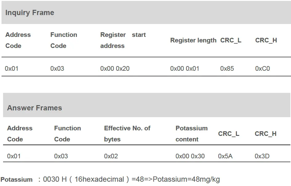
Read the Soil NPK Value from Device Address 0x01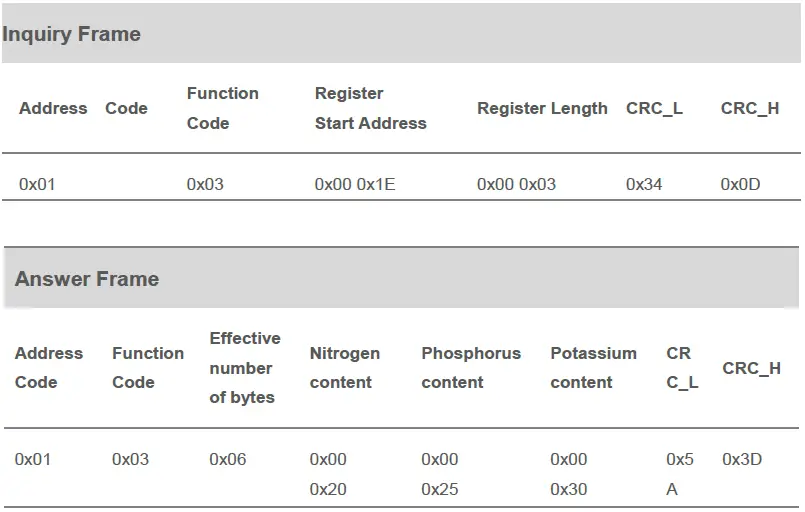
NPK content:
- 0020 H(hexadecimal )=32=>Nitrogen=32mg/kg
- 0025 H(hexadecimal )=37=>Phosphorus=37mg/kg
- 0030 H(hexadecimal )=48=>Potassium=48mg/kg
Reading the value of soil nitrogen at device address 0x01
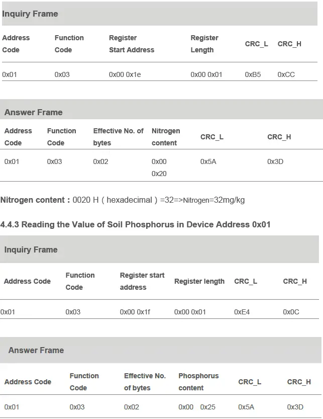
Phosphorus content:0025 H(16hexadecimal)=37=>Phosphorus=37mg/kg
Reading the Value of Soil Potassium in Device Address 0x01