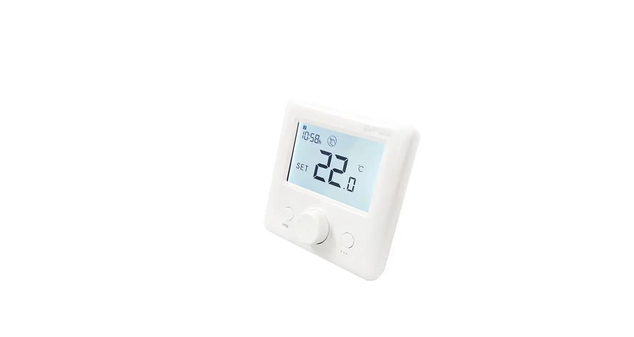
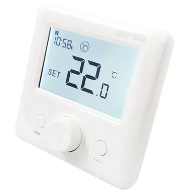
BVF 24-F RF Room Thermostat
User manual
RF room thermostat (sender only)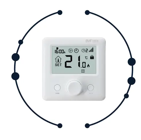
TECHNICAL DATA
- Thermostat Operating Voltage: 2 x AAA 1.5V, alkaline batteries
- Backup Storage: EEPROM
- Frequency:868MHz
- Receiver capacity:
- 24-X 3600W/16A
- 24-A 3600W/16A
- Switching options: 5+1+1 day, 4 periods each day
- Temperature settings: 5°C ~ 35°C, 0.5°C increments
- Accuracy: +/- 0.5°C
- Thermostat dimensions: 86mm x 86mm x 26.5mm
- Color: White
- IP protection rating: 20
- Certification: CE
PRODUCT FEATURES
- Large display can be clearly read with the background lighting
- Easy to fit thermostat and receiver
- Knob button make it easy to use.
- 4 periods of each day programmable (5+1+1)
- The display shows the set and the measured temperature
- Compatible with 24-A, 24-P, 24-X

CODE PAIRING
According to the receiver’s manual.
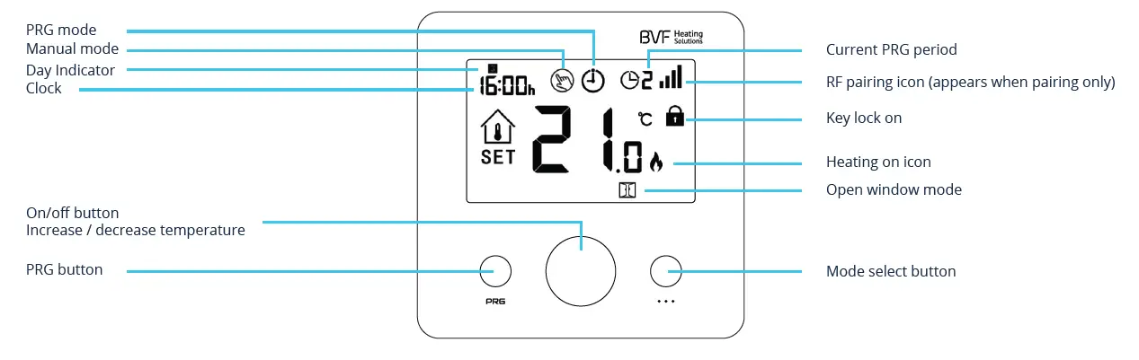
MODE SELECT
Press … button to select PRG mode / manual mode / away mode.
CLOCK
Under thermostat on, press and hold … button for 3s, set the clock by adjusting the knob to left or right, each press of … button will go to next item setting.
PRG SETTINGS
Press and hold PRG button for 3s to enter program setting. Set the schedule (Weekday-Period-Start time-Temp.) by adjusting knob to left or right to change value setting, each press of Weekday is fixed( Mon.-Fri., Sat., Sun.)
Default values
| Period | Wake up 1 | Leave Home 2 | Return Home 3 | Sleep 4 | ||||
| Time | Temp. | Time | Temp. | Time | Temp. | Time | Temp. | |
| 1-5 (Mon.-Fri.) | 7:00 | 22°C | 8:30 | 19°C | 17:00 | 22°C | 22:00 | 19°C |
| 6 (Sat.) | 8:00 | 22°C | 8:30 | 22°C | 17:00 | 22°C | 22:00 | 19°C |
| 7 (Sun.) | 8:00 | 22°C | 8:30 | 22°C | 17:00 | 22°C | 22:00 | 19°C |
KEY-LOCK FUNCTION
Under child lock ON (refer to menu12 of parameter setting ), the buttons will be locked once backlight off, if so you can long press on/off button to unlock.
OPEN WINDOW DETECTION (OWD) FUNCTION
When the Open Window detect function is enabled in the parameter setting, the system will automatically stop heating when it detects a sudden drop of room temperature (2°C in 15 minutes as default). This is normally caused when a window or door is opened without turning off the heating device. The device will return to the previous mode of operation after 30mins, then disappear. Press any button will exit OWD function during the heating off period.
PARAMETER SETTINGS
Turn off the thermostat, long-press Knob button to enter the parameter setting page, each press of the… button will go to next item setting. By adjust knob to left or right to change value setting. After setting, long press knob button to exit.
| Menu | Description | Range | Default |
| 01 | Temp. Offset | -8°C ~ 8°C | 0 |
| 02 | Set Point Max. | 5°C ~ 35°C | 35°C |
| 03 | Set Point Min. | 5°C ~ 35°C | 5°C |
| 04 | Sensor Select | 0: I or E 1: I & E 2: I 3: E (I = Internal sensor, E = External sensor) | 2 |
| 05 | Frost Protection Temp. | Off; 5°C ~15°C | 5°C |
| 06 | Surface Temp. Display | Read Only | |
| 07 | High Temp. Protection | 5°C ~ 80°C | 32°C |
| 09 | Dead zone | 0°C ~ 3°C | 0°C |
| 11 | Factory reset | Choose “rE” then press on/off button for 5s, until thermostat restart | |
| 12 | Key lock | 0 – off, 1 – on | 0 |
| 14 | OWD function ON/OFF select | 0 – off, 1 – on | 0 |
| 15 | OWD Detect Time Select | 2 ~ 30 mins | 15 mins |
| 16 | OWD Drop temp. select (within detect time) | 2 / 3 / 4°C | 2°C |
| 17 | OWD Delay time select (Return to previous working status) | 10 ~ 60 mins | 30 mins |
| 18 | The temp. diff to exit high protection mode | 1°C ~ 3°C | 1°C |
| 19 | External sensor temp. offset | -8°C ~ 8°C | 0 |
| 20 | Energy optimisation | 1: electric radiator 3: ceiling heating 2: heating panel 4: floor heating | 2 |
| 21 | Software version | ||
| 22 | Software version |
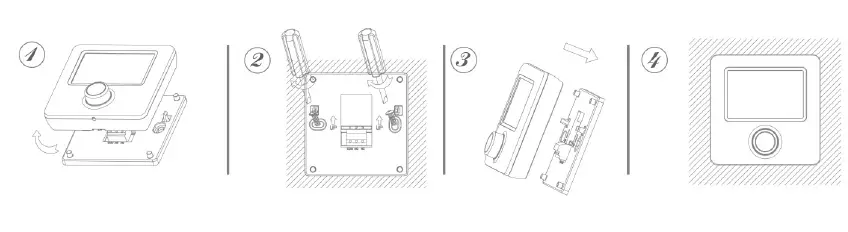
INSTALLATION
Mount the thermostat at eye level. Read the instructions fully so you get the best from our product. Do not install near to a direct heat source as this will affect functionality. Do not push hard on the LCD screen as this may cause irreparable damage.
- Step 1: Carefully separate the front half from the back plate.
- Step 2: Screw the thermostat back plate securely on wall with provided screws
- Step 3: Clip the front of the thermostat onto the back plate.

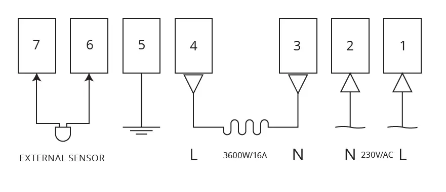
16A RF receiver
TECHNICAL DATA
- Receiver Current Load 230V, 50/60Hz
- Capacity max 3600W/16A.
- External sensor NTC 10kΩ @ 25°C 868MHz
- Frequency 86mm x 86mm x 26mm
- Dimensions65 mm diameter,
- Relay inst. dimensions min. 55mm depth
- Color White
- IP protect rating IP 20
- Certification CE

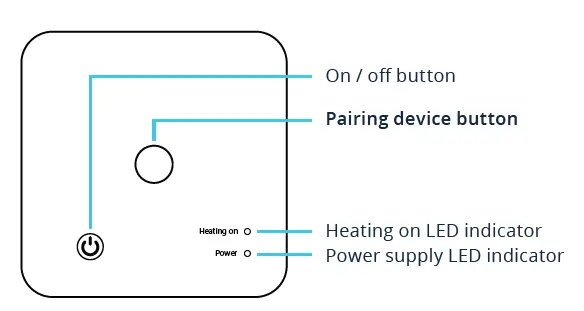
PAIRING WITH 24-F
Enter the parameter setting page (see the details in the 24-F manual), then select the appropriate setting in sensor select menu nr. 4 as follows:
- Use Setting 1 for floor heating (double sensor setting)
- Choose Setting 3 for comfort floor heating (floor sensor only)
- Setting 0 is only applied to infrapanel heating with a single-room sensor function
Use Setting 2 solely for 24-A and 24-P receivers (room sensor only, unable to work with the 24-X unit)
Important notice: according to the settings, you can connect only the same type of receiver with a single 24-F controller.
Pairing process
- Long press the code pairing button on the receiver until LED flash.
- Turn off the sender by pressing the on/off button, and long-press… until the RF code shows on the screen (XXXX), then please rotate the button to left or right, the icon
- Wait for a while till
 the icon stops flashing. Code pairing finished.