![]() ELECTRICAL CURAFDB10A-01 Tall Body Combined AFDD
ELECTRICAL CURAFDB10A-01 Tall Body Combined AFDD
Instruction Manual
Fortress Circuit Protections AFDD
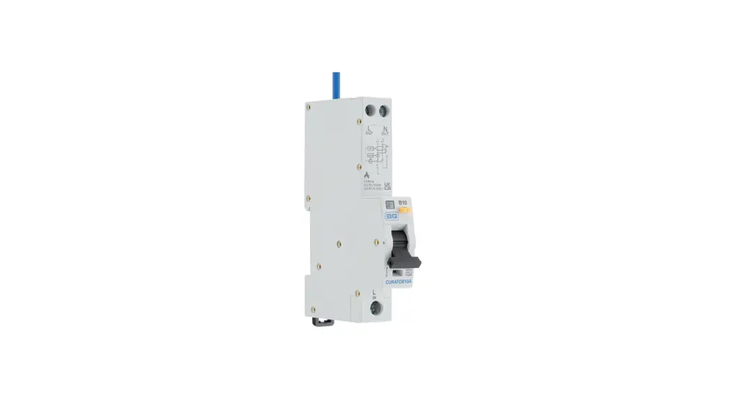
Combined RCBO/AFDD
Electronic line voltage dependent device 1P + N (switch neutral) with flying lead insulated flexible copper wire
Installation Advice
This device must be installed by a qualified skilled person (electrically) in accordance with all relevant regulations including wiring regulations BS7671.
Insulation resistance test:
SWITCH OFF the device before an insulation resistance test between live conductors of the final load circuit as defined in the standard BS EN 62606. During commissioning the device must be tested using the test button, marked “T”; the device must trip immediately. This test must be repeated throughout the installed life of the device at intervals defined by relevant regulations including wiring regulations BS7671. This verifies the electrical and mechanical parts of the device only. Only for use within BG Consumer Units.
Test after installation
The interference transmission requirements as defined in the standards CISPR 14-1 and DIN EN 61000-6-3 (limit value class B) must be observed for the devices operated in the electrical installation (equipment). Non-compliant or defective devices (equipment) may cause interference which can influence the response sensitivity of the arc fault detection device.
Description
| B or C | MCB tripping characteristics |
| Type A RCD classification | |
| 30mA | Rated residual operating current I Δ n |
| ~230V/240V | Rated voltage Un 50/60 Hz |
| Rated short circuit breaking capacity (A) / lcn=6000A | |
| Energy limiting class | |
| Ambient temperature range -25°C to + 40°C |
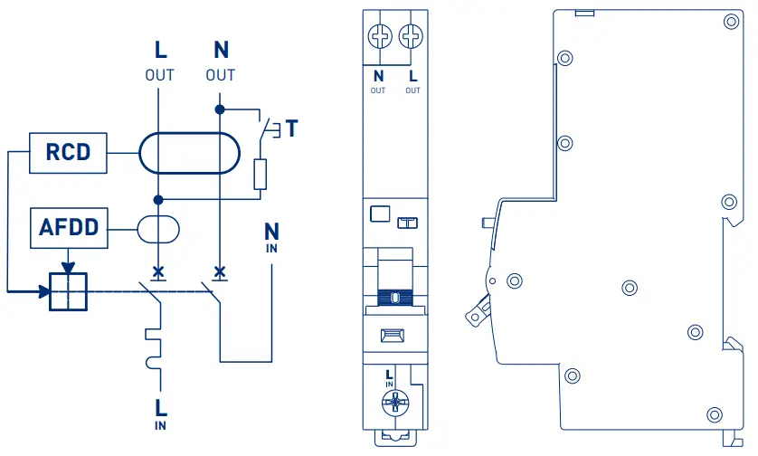
Connection Diagram
LED indication
| LED Indication after tripping and re closing | Description |
 | Overcurrent Fault or Residual Current Fault |
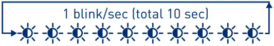 | Series Arcing Fault or Parallel Arcing Fault |
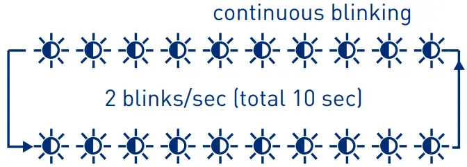 | Overvoltage Fault (U>275V) |
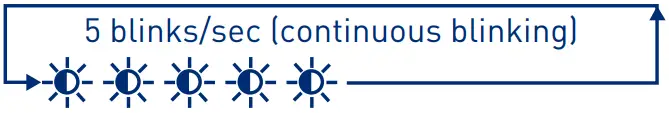 | Internal Self-Test Fault |
Torque settings
| Cross section | Screw torque | |
| Line terminal | 16mm² | 2Nm |
| Load terminals | 10mm² | 1.2Nm |
Notes
| ALWAYS SWITCH OFF THE MAINS POWER BEFORE INSTALLING THIS DEVICE INTO A CONSUMER UNIT | |
| COMPLETE ALL CONNECTIONS, INCLUDING BLUE N FLYING LEAD,BEFORE RESTORING MAINS POWER |
AFDD part operating criteria
Series Arcing Fault
| Load current (A) | Maximum allowed tripping time (s) |
| 2.5 | 1 |
| 5 | 0.5 |
| 10 | 0.25 |
| 16 | 0.15 |
| 32 | 0.12 |
| 40 | 0.12 |
Parallel Arcing Fault
| Test current (A) | Maximum allowed number of arcing half-waves within 0.5s (N) |
| 75 | 12 |
| 100 | 10 |
| 150 | 8 |
| 200 | 8 |
| 300 | 8 |
| 500 | 8 |
Batch Code explanation
yyWxx Manufacturing date code, year of manufacture (yy) and week of manufacture (Wxx)
Address/Helpline
Luceco PLC
Stafford Park 1
Telford TF3 3BD
ENGLAND
(EU) Luceco SE
C/ Bobinadora 1-5
08302 Mataró
SPAIN
If you have further technical assistance you can get in touch with our
Technical Helpline on:
+44 (0)3300 249 279
[email protected]
Environmental Protection
![]() This symbol is known as the “Crossed-out Wheelie Bin Symbol”. When this symbol is marked on a product or battery, it means that it should not be disposed of with your general household waste. Some chemicals contained within electrical/electronic products or batteries can be harmful to health and the environment. Only dispose of electrical/electronic/battery items in separate collection schemes, which cater for the recovery and recycling of materials contained within. Your co-operation is vital to ensure the success of these schemes and for the protection of the environment.
This symbol is known as the “Crossed-out Wheelie Bin Symbol”. When this symbol is marked on a product or battery, it means that it should not be disposed of with your general household waste. Some chemicals contained within electrical/electronic products or batteries can be harmful to health and the environment. Only dispose of electrical/electronic/battery items in separate collection schemes, which cater for the recovery and recycling of materials contained within. Your co-operation is vital to ensure the success of these schemes and for the protection of the environment.
![]()


